How to Use PIC16F877A: Examples, Pinouts, and Specs
Introduction
The PIC16F877A is an 8-bit microcontroller manufactured by Microchip Technology. It is a highly versatile and widely used microcontroller in embedded systems, offering a robust set of features that make it suitable for a variety of applications. With 40 pins, 368 bytes of RAM, 256 bytes of EEPROM, and a 14-bit instruction set, the PIC16F877A is designed to handle complex tasks while maintaining ease of programming.
Explore Projects Built with PIC16F877A


Explore Projects Built with PIC16F877A
Common Applications and Use Cases
- Home automation systems
- Industrial control systems
- Robotics and motor control
- Data acquisition systems
- Educational projects and prototyping
- IoT (Internet of Things) devices
Technical Specifications
The following table outlines the key technical details of the PIC16F877A microcontroller:
| Parameter | Value |
|---|---|
| Manufacturer | Microchip Technology |
| Part ID | Controller |
| Architecture | 8-bit |
| Instruction Set | 14-bit |
| Operating Voltage | 2.0V to 5.5V |
| Flash Program Memory | 14 KB (8,192 words) |
| Data Memory (RAM) | 368 bytes |
| EEPROM | 256 bytes |
| I/O Pins | 33 |
| Timers | 3 (Timer0, Timer1, Timer2) |
| Communication Interfaces | USART, SPI, I2C |
| ADC Resolution | 10-bit (8 channels) |
| Oscillator Frequency | Up to 20 MHz |
| Package Types | DIP-40, PLCC-44, TQFP-44 |
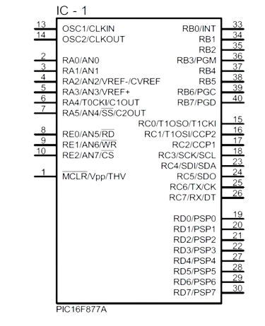
Pin Configuration and Descriptions
The PIC16F877A has 40 pins, each with specific functions. Below is a summary of the pin configuration:
| Pin Number | Pin Name | Description |
|---|---|---|
| 1 | MCLR/VPP | Master Clear (Reset) input or programming voltage |
| 2-7 | RA0-RA5 | Port A: Analog/Digital I/O pins |
| 8 | VSS | Ground |
| 9-10 | OSC1/OSC2 | Oscillator input/output |
| 11-18 | RB0-RB7 | Port B: Digital I/O pins |
| 19 | VDD | Positive supply voltage |
| 20-27 | RC0-RC7 | Port C: Digital I/O pins |
| 28-33 | RD0-RD7 | Port D: Digital I/O pins |
| 34-40 | RE0-RE2, VSS, VDD | Port E: Digital I/O pins, Ground, Power |
For a complete pinout diagram, refer to the official datasheet provided by Microchip Technology.
Usage Instructions
How to Use the PIC16F877A in a Circuit
- Power Supply: Connect the VDD pin to a 5V power source and the VSS pin to ground.
- Oscillator Setup: Connect an external crystal oscillator (e.g., 20 MHz) between OSC1 and OSC2 pins, along with appropriate capacitors.
- Reset Circuit: Connect a pull-up resistor (typically 10 kΩ) to the MCLR pin for proper reset functionality.
- I/O Configuration: Configure the I/O pins (RA, RB, RC, RD, RE) as input or output in the software.
- Programming: Use an ICSP (In-Circuit Serial Programming) tool to load your program into the microcontroller.
Important Considerations and Best Practices
- Decoupling Capacitors: Place 0.1 µF decoupling capacitors near the VDD and VSS pins to reduce noise.
- Unused Pins: Configure unused pins as outputs or connect them to ground through pull-down resistors to avoid floating states.
- Clock Source: Ensure the oscillator frequency matches the requirements of your application.
- Programming Voltage: During programming, ensure the MCLR pin receives the correct voltage (typically 13V for high-voltage programming).
Example Code for Arduino UNO Integration
The PIC16F877A can communicate with an Arduino UNO via UART. Below is an example of how to send data from the Arduino to the PIC16F877A:
// Arduino UNO Code: Sending data to PIC16F877A via UART
void setup() {
  Serial.begin(9600); // Initialize UART communication at 9600 baud rate
}

void loop() {
  Serial.println("Hello, PIC16F877A!"); // Send a message to the PIC
  delay(1000); // Wait for 1 second before sending the next message
}
On the PIC16F877A side, configure the USART module to receive the data. Refer to the PIC16F877A datasheet for detailed USART setup instructions.
Troubleshooting and FAQs
Common Issues and Solutions
Microcontroller Not Responding
- Cause: Incorrect power supply or oscillator configuration.
- Solution: Verify the VDD and VSS connections and ensure the oscillator circuit is properly configured.
Program Not Uploading
- Cause: Faulty ICSP connection or incorrect programming voltage.
- Solution: Check the ICSP connections and ensure the MCLR pin receives the correct programming voltage.
I/O Pins Not Functioning
- Cause: Pins not configured correctly in the software.
- Solution: Double-check the TRIS registers to ensure the pins are set as input or output as required.
ADC Not Working
- Cause: Incorrect ADC configuration or reference voltage.
- Solution: Verify the ADCON0 and ADCON1 register settings and ensure the reference voltage is stable.
FAQs
Q: Can the PIC16F877A operate at 3.3V?
A: Yes, the PIC16F877A can operate at voltages as low as 2.0V, but ensure the oscillator and peripherals are compatible with the lower voltage.
Q: How do I protect the microcontroller from voltage spikes?
A: Use TVS diodes or zener diodes on the power supply lines and add decoupling capacitors near the VDD and VSS pins.
Q: Can I use the internal oscillator instead of an external crystal?
A: No, the PIC16F877A does not have an internal oscillator. An external oscillator is required.
For further details, consult the official datasheet and application notes provided by Microchip Technology.