How to Use MPXV7002DP Pressure Sensor: Examples, Pinouts, and Specs
Introduction
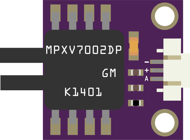
The MPXV7002DP is a differential pressure sensor that provides a voltage output proportional to the pressure difference between its two ports. It is designed for applications requiring accurate pressure measurements in a compact form factor, suitable for both air and non-corrosive gases. This sensor is widely used in applications such as HVAC systems, medical devices, and industrial process control, where precise pressure monitoring is critical.
Explore Projects Built with MPXV7002DP Pressure Sensor
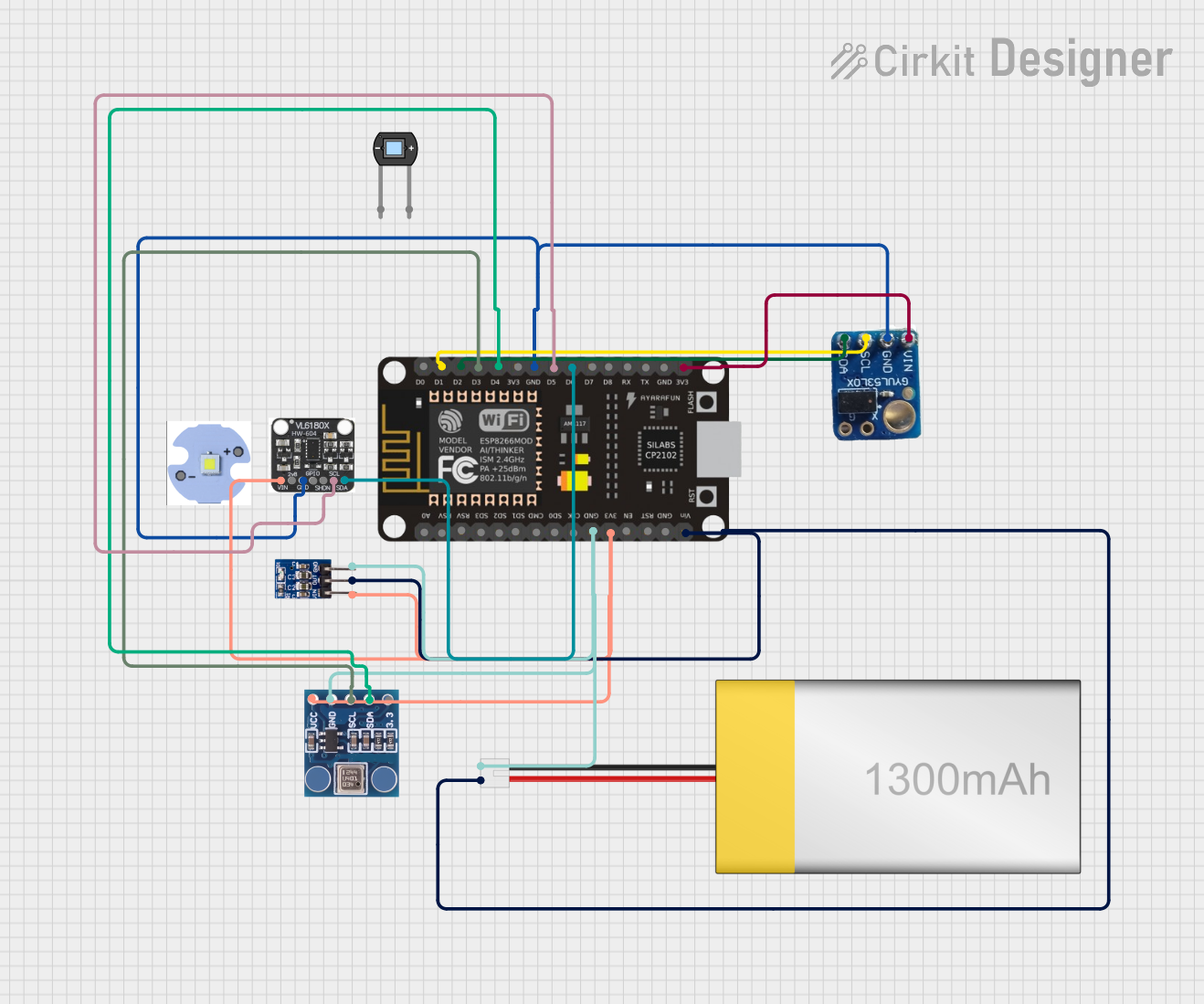

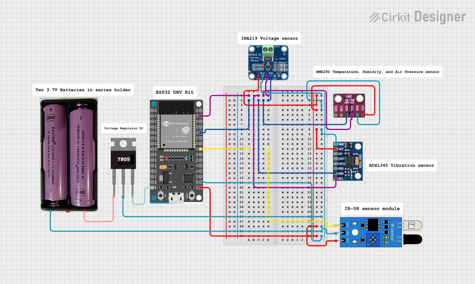
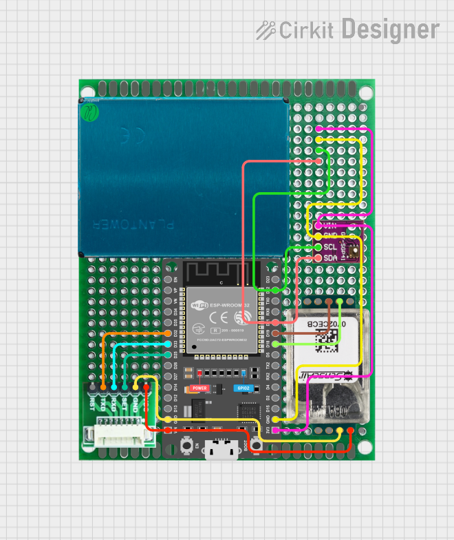
Explore Projects Built with MPXV7002DP Pressure Sensor
Common Applications:
- Airflow measurement in HVAC systems
- Medical devices such as ventilators and CPAP machines
- Industrial process control and monitoring
- Leak detection systems
- Altitude and barometric pressure measurement
Technical Specifications
Key Technical Details:
- Pressure Range: ±2 kPa (±0.29 psi)
- Supply Voltage: 5 V DC (typical)
- Output Voltage: 0.5 V to 4.5 V (proportional to pressure)
- Accuracy: ±2.5% of full-scale span
- Response Time: 1 ms
- Operating Temperature Range: -40°C to +125°C
- Media Compatibility: Air and non-corrosive gases
- Package Type: Small Outline Package (SOP)
Pin Configuration and Descriptions:
The MPXV7002DP has a 3-pin configuration. Below is the pinout description:
| Pin Number | Pin Name | Description |
|---|---|---|
| 1 | VOUT | Analog output voltage proportional to |
| the pressure difference | ||
| 2 | GND | Ground (0 V reference) |
| 3 | VCC | Power supply input (5 V DC) |
Port Configuration:
The sensor has two ports for differential pressure measurement:
- P1 (Positive Port): Higher pressure input
- P2 (Negative Port): Lower pressure input
The output voltage increases as the pressure at P1 becomes greater than the pressure at P2.
Usage Instructions
How to Use the MPXV7002DP in a Circuit:
- Power Supply: Connect the VCC pin to a stable 5 V DC power source and the GND pin to the ground of the circuit.
- Output Signal: Connect the VOUT pin to an analog input pin of a microcontroller or ADC (Analog-to-Digital Converter) to read the sensor's output voltage.
- Pressure Ports: Attach tubing or connectors to the P1 and P2 ports for measuring the pressure difference. Ensure the media is compatible (air or non-corrosive gases).
- Signal Processing: Use the output voltage to calculate the pressure difference using the formula: [ \text{Pressure Difference (kPa)} = \frac{\text{VOUT} - 2.5}{2.0} ] where VOUT is the sensor's output voltage in volts.
Important Considerations:
- Ensure the sensor is not exposed to corrosive gases or liquids, as this may damage the internal components.
- Avoid applying excessive pressure beyond the specified range (±2 kPa) to prevent permanent damage.
- Use proper decoupling capacitors (e.g., 0.1 µF) near the VCC pin to reduce noise and ensure stable operation.
- If using long tubing, ensure it is airtight to avoid measurement errors due to leaks.
Example: Connecting MPXV7002DP to an Arduino UNO
Below is an example of how to interface the MPXV7002DP with an Arduino UNO to measure differential pressure:
// MPXV7002DP Pressure Sensor Example with Arduino UNO
// Reads the sensor's output voltage and calculates the pressure difference

const int sensorPin = A0; // Analog pin connected to VOUT of the sensor
float sensorVoltage = 0.0; // Variable to store the sensor's output voltage
float pressureDifference = 0.0; // Variable to store the calculated pressure

void setup() {
  Serial.begin(9600); // Initialize serial communication for debugging
  pinMode(sensorPin, INPUT); // Set the sensor pin as input
}

void loop() {
  // Read the analog value from the sensor (0-1023)
  int analogValue = analogRead(sensorPin);

  // Convert the analog value to voltage (assuming 5V reference)
  sensorVoltage = analogValue * (5.0 / 1023.0);

  // Calculate the pressure difference in kPa
  pressureDifference = (sensorVoltage - 2.5) / 2.0;

  // Print the results to the Serial Monitor
  Serial.print("Sensor Voltage: ");
  Serial.print(sensorVoltage);
  Serial.print(" V, Pressure Difference: ");
  Serial.print(pressureDifference);
  Serial.println(" kPa");

  delay(1000); // Wait for 1 second before the next reading
}
Notes:
- Ensure the Arduino's analog reference voltage is set to 5 V for accurate readings.
- Use a stable 5 V power supply for the sensor to minimize noise and fluctuations.
Troubleshooting and FAQs
Common Issues and Solutions:
No Output Voltage or Incorrect Readings:
- Verify the power supply connections (VCC and GND).
- Ensure the sensor is not exposed to corrosive or liquid media.
- Check for loose or damaged wires.
Fluctuating or Noisy Output:
- Add a decoupling capacitor (e.g., 0.1 µF) near the VCC pin.
- Ensure the power supply is stable and free from noise.
Output Voltage Stuck at 2.5 V:
- Verify that there is a measurable pressure difference between P1 and P2.
- Check for blockages or leaks in the tubing connected to the ports.
Sensor Damage:
- Avoid applying pressure beyond the specified range (±2 kPa).
- Ensure the sensor is used within the recommended temperature range.
FAQs:
Q1: Can the MPXV7002DP measure absolute pressure?
A1: No, the MPXV7002DP is a differential pressure sensor and measures the pressure difference between its two ports (P1 and P2).
Q2: What happens if I reverse the P1 and P2 connections?
A2: The sensor will still function, but the output voltage will decrease as the pressure at P2 becomes greater than the pressure at P1.
Q3: Can I use the MPXV7002DP with a 3.3 V microcontroller?
A3: The sensor requires a 5 V power supply for proper operation. However, you can use a voltage divider or level shifter to interface the 5 V output with a 3.3 V microcontroller.
Q4: How do I protect the sensor from overpressure?
A4: Use a pressure relief valve or restrictor to limit the pressure applied to the sensor within its specified range.
By following this documentation, you can effectively integrate the MPXV7002DP into your projects for accurate and reliable pressure measurements.