How to Use X8-20: Examples, Pinouts, and Specs
Introduction
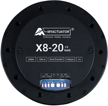
The X8-20 is a versatile programmable logic controller (PLC) developed by Myactuator. It is designed for industrial automation and control applications, offering a robust and reliable solution for managing complex processes. The X8-20 features multiple input/output (I/O) channels, supports a variety of communication protocols, and is engineered for ease of programming and integration into existing systems.
Explore Projects Built with X8-20
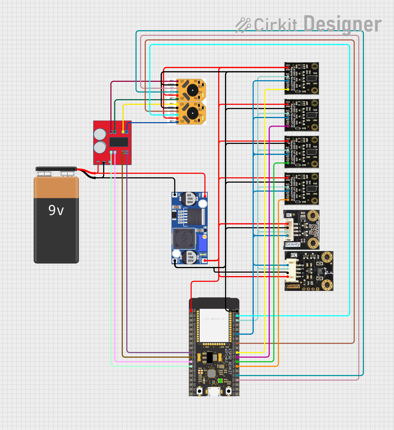


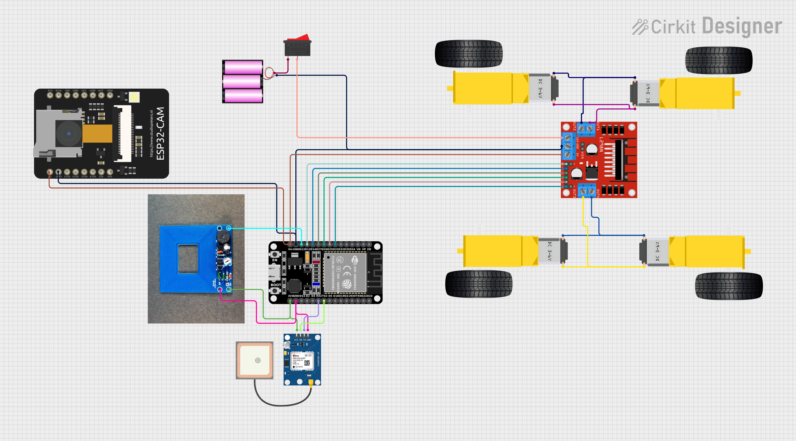
Explore Projects Built with X8-20
Common Applications and Use Cases
- Industrial automation and process control
- Machine control and monitoring
- Building management systems (BMS)
- Conveyor systems and robotics
- Data acquisition and remote monitoring
Technical Specifications
The X8-20 is built to handle demanding industrial environments while maintaining high performance and flexibility. Below are its key technical specifications:
General Specifications
| Parameter | Value |
|---|---|
| Supply Voltage | 24V DC |
| Power Consumption | 10W (typical) |
| Operating Temperature | -20°C to 60°C |
| Storage Temperature | -40°C to 85°C |
| Dimensions | 120mm x 90mm x 60mm |
| Weight | 450g |
| Mounting Type | DIN Rail |
Input/Output Specifications
| Type | Channels | Voltage Range | Description |
|---|---|---|---|
| Digital Inputs | 8 | 0-24V DC | Optically isolated inputs |
| Digital Outputs | 8 | 0-24V DC | Relay or transistor outputs |
| Analog Inputs | 4 | 0-10V or 4-20mA | Configurable for voltage/current |
| Analog Outputs | 2 | 0-10V or 4-20mA | Configurable for voltage/current |
Communication Interfaces
| Protocol | Description |
|---|---|
| RS-485 | Modbus RTU support |
| Ethernet | Modbus TCP/IP, HTTP, MQTT |
| USB | Programming and debugging |
| CAN | CANopen protocol support |
Pin Configuration
Power and Communication
| Pin Number | Label | Description |
|---|---|---|
| 1 | V+ | 24V DC Positive Supply |
| 2 | V- | 24V DC Negative Supply |
| 3 | GND | Ground |
| 4 | RS485+ | RS-485 Positive Line |
| 5 | RS485- | RS-485 Negative Line |
| 6 | CAN_H | CAN High Line |
| 7 | CAN_L | CAN Low Line |
Digital Inputs and Outputs
| Pin Number | Label | Description |
|---|---|---|
| 8-15 | DI1-DI8 | Digital Input Channels 1-8 |
| 16-23 | DO1-DO8 | Digital Output Channels 1-8 |
Analog Inputs and Outputs
| Pin Number | Label | Description |
|---|---|---|
| 24-27 | AI1-AI4 | Analog Input Channels 1-4 |
| 28-29 | AO1-AO2 | Analog Output Channels 1-2 |
Usage Instructions
The X8-20 is designed for ease of use in industrial environments. Follow the steps below to integrate and program the device:
Step 1: Powering the X8-20
- Connect a 24V DC power supply to the V+ and V- terminals.
- Ensure the power supply is stable and within the specified voltage range.
Step 2: Connecting Inputs and Outputs
- Digital Inputs: Connect sensors or switches to the DI1-DI8 terminals. Ensure the input voltage does not exceed 24V DC.
- Digital Outputs: Connect actuators, relays, or other devices to the DO1-DO8 terminals.
- Analog Inputs: Configure the AI1-AI4 channels for voltage (0-10V) or current (4-20mA) as required.
- Analog Outputs: Use AO1-AO2 for controlling devices like variable frequency drives (VFDs) or proportional valves.
Step 3: Communication Setup
- Use the RS-485 or Ethernet interface for communication with other devices or systems.
- Configure the communication protocol (e.g., Modbus RTU or TCP/IP) using the provided software.
Step 4: Programming the X8-20
- Install the Myactuator programming software on your PC.
- Connect the X8-20 to your PC via the USB port.
- Use the graphical programming interface to create logic for your application.
- Upload the program to the X8-20 and test its functionality.
Example: Controlling an LED with Arduino UNO
The X8-20 can be interfaced with an Arduino UNO for additional control. Below is an example code to toggle a digital output on the X8-20:
// Example: Controlling X8-20 Digital Output with Arduino UNO
// Connect Arduino pin 7 to the X8-20's DO1 terminal

#define X8_20_DO1 7  // Define Arduino pin connected to X8-20 DO1

void setup() {
  pinMode(X8_20_DO1, OUTPUT);  // Set pin as output
}

void loop() {
  digitalWrite(X8_20_DO1, HIGH);  // Turn on the output
  delay(1000);                    // Wait for 1 second
  digitalWrite(X8_20_DO1, LOW);   // Turn off the output
  delay(1000);                    // Wait for 1 second
}
Best Practices
- Use proper shielding for communication cables to avoid interference.
- Ensure all connections are secure to prevent accidental disconnections.
- Regularly back up your programs and configurations.
Troubleshooting and FAQs
Common Issues
Device Not Powering On
- Check the power supply voltage and connections.
- Ensure the polarity of the power supply is correct.
Communication Failure
- Verify the communication protocol and settings (e.g., baud rate, parity).
- Check the integrity of the communication cables.
Inputs/Outputs Not Responding
- Ensure the connected devices are functioning properly.
- Verify the configuration of the I/O channels in the programming software.
FAQs
Q: Can the X8-20 be used in outdoor environments?
A: The X8-20 is not weatherproof. Use it in a controlled environment or within a protective enclosure.
Q: What programming languages are supported?
A: The X8-20 supports ladder logic and function block programming via the Myactuator software.
Q: How do I reset the X8-20 to factory settings?
A: Refer to the Myactuator user manual for detailed instructions on performing a factory reset.
Q: Can I expand the I/O channels?
A: Yes, the X8-20 supports expansion modules for additional I/O channels. Contact Myactuator for compatible modules.
By following this documentation, users can effectively integrate and operate the X8-20 in their automation projects.