How to Use LM2596: Examples, Pinouts, and Specs
Introduction
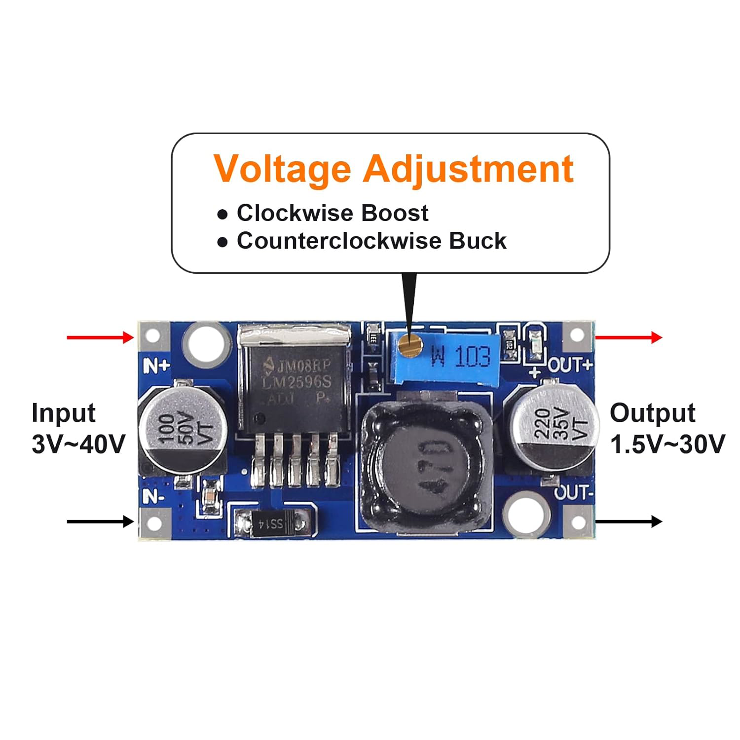
The LM2596 is a step-down (buck) voltage regulator designed to efficiently convert a higher input voltage into a stable, regulated output voltage. Manufactured under the part ID LM2596, this component is capable of delivering up to 3A of output current, making it ideal for applications requiring moderate power levels. Its wide input voltage range and high efficiency make it a popular choice for power supply circuits in embedded systems, industrial equipment, and consumer electronics.
Explore Projects Built with LM2596


Explore Projects Built with LM2596
Common Applications and Use Cases
- DC-DC power supply modules
- Battery-powered devices
- Voltage regulation for microcontrollers and sensors
- LED drivers
- Industrial automation systems
Technical Specifications
Key Technical Details
- Input Voltage Range: 4.5V to 40V
- Output Voltage Range: 1.23V to 37V (adjustable)
- Output Current: Up to 3A
- Efficiency: Up to 90% (depending on input/output conditions)
- Switching Frequency: 150 kHz (fixed)
- Thermal Shutdown: Yes
- Overcurrent Protection: Yes
- Package Types: TO-220, TO-263
Pin Configuration and Descriptions
The LM2596 is typically available in a 5-pin TO-220 or TO-263 package. Below is the pinout description:
| Pin Number | Pin Name | Description |
|---|---|---|
| 1 | VIN | Input voltage pin. Connect to the unregulated DC input voltage. |
| 2 | Output | Regulated output voltage pin. Connect to the load. |
| 3 | Ground (GND) | Ground pin. Connect to the circuit ground. |
| 4 | Feedback | Feedback pin. Used to set the output voltage via an external resistor divider. |
| 5 | ON/OFF | Enable pin. Logic high enables the regulator; logic low disables it. |
Usage Instructions
How to Use the LM2596 in a Circuit
- Input Voltage: Ensure the input voltage (VIN) is within the range of 4.5V to 40V and is at least 1.5V higher than the desired output voltage.
- Output Voltage Adjustment: Use a resistor divider network connected to the Feedback pin to set the desired output voltage. The output voltage can be calculated using the formula: [ V_{OUT} = 1.23 \times \left(1 + \frac{R1}{R2}\right) ] where R1 and R2 are the resistors in the divider network.
- Capacitors: Add input and output capacitors to stabilize the circuit. Typical values are:
- Input capacitor: 100 µF electrolytic
- Output capacitor: 220 µF electrolytic
- Inductor Selection: Choose an inductor with a suitable current rating (greater than 3A) and an inductance value between 33 µH and 100 µH, depending on the desired ripple current.
- Enable Pin: Connect the ON/OFF pin to VIN for continuous operation or control it with a microcontroller or switch.
Example Circuit
Below is a basic circuit diagram for the LM2596:
VIN ----+---- Input Capacitor ----+---- LM2596 ----+---- Output Capacitor ---- VOUT
        |                         |                |                          |
       GND                       GND              GND                        GND
Arduino UNO Example Code
The LM2596 can be used to power an Arduino UNO or other microcontrollers. Below is an example code snippet to control the ON/OFF pin of the LM2596 using a digital pin on the Arduino:
// Define the pin connected to the LM2596 ON/OFF pin
const int lm2596EnablePin = 7;

void setup() {
  // Set the pin mode for the LM2596 enable pin
  pinMode(lm2596EnablePin, OUTPUT);

  // Enable the LM2596 by setting the pin HIGH
  digitalWrite(lm2596EnablePin, HIGH);
}

void loop() {
  // Example: Toggle the LM2596 ON/OFF every 5 seconds
  digitalWrite(lm2596EnablePin, LOW); // Turn off the LM2596
  delay(5000);                        // Wait for 5 seconds
  digitalWrite(lm2596EnablePin, HIGH); // Turn on the LM2596
  delay(5000);                        // Wait for 5 seconds
}
Important Considerations and Best Practices
- Thermal Management: The LM2596 can generate heat during operation, especially at high currents. Use a heatsink or ensure proper ventilation to prevent overheating.
- Input Voltage Ripple: Use a low-ESR input capacitor to minimize voltage ripple and improve stability.
- Output Voltage Accuracy: Use precision resistors for the feedback network to achieve accurate output voltage.
- Inductor Selection: Ensure the inductor's saturation current rating exceeds the maximum output current to avoid saturation.
Troubleshooting and FAQs
Common Issues and Solutions
| Issue | Possible Cause | Solution |
|---|---|---|
| Output voltage is unstable | Insufficient input/output capacitors | Use low-ESR capacitors with recommended values. |
| Regulator overheats | Excessive load current or poor ventilation | Reduce load current or add a heatsink. |
| Output voltage is incorrect | Incorrect feedback resistor values | Verify and recalculate the resistor divider network. |
| No output voltage | ON/OFF pin is not enabled | Ensure the ON/OFF pin is connected to VIN or controlled properly. |
| High output ripple | Poor inductor or capacitor selection | Use an inductor with higher inductance and low-ESR capacitors. |
FAQs
Can the LM2596 be used for negative voltage regulation?
- No, the LM2596 is designed for positive voltage regulation only.
What is the maximum input voltage for the LM2596?
- The maximum input voltage is 40V. Exceeding this value may damage the component.
Can the LM2596 operate without a heatsink?
- It depends on the load current and input/output voltage difference. For high currents, a heatsink is recommended.
How do I calculate the inductor value for my application?
- The inductor value depends on the desired ripple current. Use the formula: [ L = \frac{(V_{IN} - V_{OUT}) \times V_{OUT}}{I_{RIPPLE} \times f_{SW} \times V_{IN}} ] where ( I_{RIPPLE} ) is the peak-to-peak ripple current and ( f_{SW} ) is the switching frequency (150 kHz).
By following this documentation, users can effectively integrate the LM2596 into their projects and troubleshoot common issues.