Cirkit Designer Logo
Cirkit Designer
Your all-in-one circuit design IDE
Home / 
Component Documentation

How to Use CC1101: Examples, Pinouts, and Specs

Image of CC1101
Cirkit Designer LogoDesign with CC1101 in Cirkit Designer

Introduction

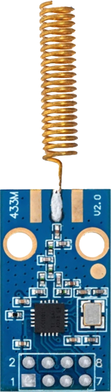
The CC1101 is a versatile, low-power RF transceiver designed for use in the ISM (Industrial, Scientific, and Medical) and SRD (Short Range Device) frequency bands. It supports various modulation formats and has a flexible data rate, making it suitable for a wide range of applications. Common applications include remote controls, home automation, wireless sensor networks, and security systems.

Explore Projects Built with CC1101

Use Cirkit Designer to design, explore, and prototype these projects online. Some projects support real-time simulation. Click "Open Project" to start designing instantly!
Satellite-Based Timing and Navigation System with SDR and Atomic Clock Synchronization
Image of GPS 시스템 측정 구성도_Confirm: A project utilizing CC1101 in a practical application
This circuit appears to be a complex system involving power supply management, GPS and timing synchronization, and data communication. It includes a SI-TEX G1 Satellite Compass for GPS data, an XHTF1021 Atomic Rubidium Clock for precise timing, and Ettus USRP B200 units for software-defined radio communication. Power is supplied through various SMPS units and distributed via terminal blocks and DC jacks. Data communication is facilitated by Beelink MINI S12 N95 computers, RS232 splitters, and a 1000BASE-T Media Converter for network connectivity. RF Directional Couplers are used to interface antennas with the USRP units, and the entire system is likely contained within cases for protection and organization.
Cirkit Designer LogoOpen Project in Cirkit Designer
Battery-Powered Raspberry Pi Pico GPS Tracker with Sensor Integration
Image of Copy of CanSet v1: A project utilizing CC1101 in a practical application
This circuit is a data acquisition and communication system powered by a LiPoly battery and managed by a Raspberry Pi Pico. It includes sensors (BMP280, MPU9250) for environmental data, a GPS module for location tracking, an SD card for data storage, and a WLR089-CanSAT for wireless communication. The TP4056 module handles battery charging, and a toggle switch controls power distribution.
Cirkit Designer LogoOpen Project in Cirkit Designer
Battery-Powered Emergency Alert System with NUCLEO-F072RB, SIM800L, and GPS NEO 6M
Image of women safety: A project utilizing CC1101 in a practical application
This circuit is an emergency alert system that uses a NUCLEO-F072RB microcontroller to send SMS alerts and make calls via a SIM800L GSM module, while obtaining location data from a GPS NEO 6M module. The system is powered by a Li-ion battery and includes a TP4056 module for battery charging and protection, with a rocker switch to control power to the microcontroller.
Cirkit Designer LogoOpen Project in Cirkit Designer
ESP8266 Multi-Tool with RFID, IR, RF, and Wi-Fi Control
Image of clipper 1: A project utilizing CC1101 in a practical application
This circuit is a multi-functional tool based on the ESP-8266 microcontroller, integrating RFID, IR, RF, and Wi-Fi capabilities. It includes an RFID reader, IR transmitter and receiver, RF module, SD card module, and an I2C LCD for user interaction, with pushbuttons for navigation and control.
Cirkit Designer LogoOpen Project in Cirkit Designer

Explore Projects Built with CC1101

Use Cirkit Designer to design, explore, and prototype these projects online. Some projects support real-time simulation. Click "Open Project" to start designing instantly!
Image of GPS 시스템 측정 구성도_Confirm: A project utilizing CC1101 in a practical application
Satellite-Based Timing and Navigation System with SDR and Atomic Clock Synchronization
This circuit appears to be a complex system involving power supply management, GPS and timing synchronization, and data communication. It includes a SI-TEX G1 Satellite Compass for GPS data, an XHTF1021 Atomic Rubidium Clock for precise timing, and Ettus USRP B200 units for software-defined radio communication. Power is supplied through various SMPS units and distributed via terminal blocks and DC jacks. Data communication is facilitated by Beelink MINI S12 N95 computers, RS232 splitters, and a 1000BASE-T Media Converter for network connectivity. RF Directional Couplers are used to interface antennas with the USRP units, and the entire system is likely contained within cases for protection and organization.
Cirkit Designer LogoOpen Project in Cirkit Designer
Image of Copy of CanSet v1: A project utilizing CC1101 in a practical application
Battery-Powered Raspberry Pi Pico GPS Tracker with Sensor Integration
This circuit is a data acquisition and communication system powered by a LiPoly battery and managed by a Raspberry Pi Pico. It includes sensors (BMP280, MPU9250) for environmental data, a GPS module for location tracking, an SD card for data storage, and a WLR089-CanSAT for wireless communication. The TP4056 module handles battery charging, and a toggle switch controls power distribution.
Cirkit Designer LogoOpen Project in Cirkit Designer
Image of women safety: A project utilizing CC1101 in a practical application
Battery-Powered Emergency Alert System with NUCLEO-F072RB, SIM800L, and GPS NEO 6M
This circuit is an emergency alert system that uses a NUCLEO-F072RB microcontroller to send SMS alerts and make calls via a SIM800L GSM module, while obtaining location data from a GPS NEO 6M module. The system is powered by a Li-ion battery and includes a TP4056 module for battery charging and protection, with a rocker switch to control power to the microcontroller.
Cirkit Designer LogoOpen Project in Cirkit Designer
Image of clipper 1: A project utilizing CC1101 in a practical application
ESP8266 Multi-Tool with RFID, IR, RF, and Wi-Fi Control
This circuit is a multi-functional tool based on the ESP-8266 microcontroller, integrating RFID, IR, RF, and Wi-Fi capabilities. It includes an RFID reader, IR transmitter and receiver, RF module, SD card module, and an I2C LCD for user interaction, with pushbuttons for navigation and control.
Cirkit Designer LogoOpen Project in Cirkit Designer

Technical Specifications

Key Technical Details

  • Frequency Bands: 300-348 MHz, 387-464 MHz, and 779-928 MHz
  • Modulation: FSK, GFSK, ASK/OOK, 4-FSK, MSK, and OOK
  • Data Rate: Programmable from 0.6 to 600 kbps
  • Supply Voltage: 1.8-3.6V
  • Current Consumption: 15.6 mA in RX, 33 mA in TX (at +10 dBm)
  • Sensitivity: -116 dBm at 1.2 kbps
  • Output Power: Up to +12 dBm
  • Operating Temperature Range: -40°C to +85°C

Pin Configuration and Descriptions

Pin Number Name Description
1 VDD Power supply voltage
2 SI Serial data input
3 SO Serial data output
4 CSn Chip select (active low)
5 SCLK Serial clock input
6 GDO2 General digital output 2
7 GDO0 General digital output 0
8 GND Ground

Usage Instructions

Integration into a Circuit

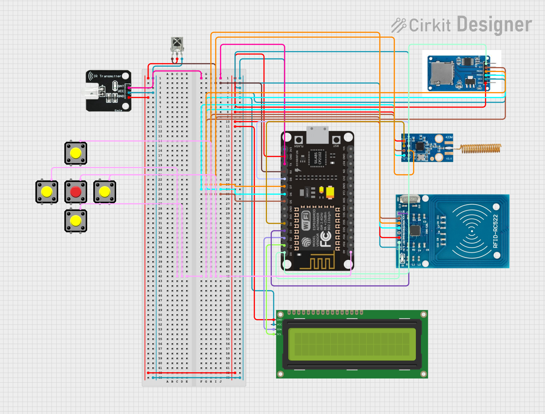
To use the CC1101 in a circuit, connect the VDD pin to a power supply within the specified voltage range and the GND pin to the system ground. The SI, SO, CSn, and SCLK pins are used for SPI communication with a microcontroller, such as an Arduino UNO. The GDO0 and GDO2 pins can be configured to provide various status signals and outputs.

Best Practices

  • Ensure that the power supply is clean and within the specified voltage range.
  • Use decoupling capacitors close to the VDD pin to filter out noise.
  • Keep the antenna path as clear as possible from other metal objects.
  • Follow the recommended PCB layout guidelines provided in the CC1101 datasheet.

Example Code for Arduino UNO

#include <SPI.h>

// Define the CC1101 pin connections to the Arduino
const int CS_PIN = 10;
const int GDO0 = 2; // Can be configured in the CC1101

void setup() {
  // Initialize the SPI interface
  SPI.begin();
  pinMode(CS_PIN, OUTPUT);
  digitalWrite(CS_PIN, HIGH); // Ensure CS is inactive (HIGH)
  pinMode(GDO0, INPUT); // Configure GDO0 as input if used
}

void loop() {
  // Example code to send a simple "Hello" message
  sendMessage("Hello");
  delay(1000);
}

void sendMessage(const char *message) {
  selectCC1101(); // Select the CC1101 transceiver
  // Write your code to configure and send the message
  // ...
  deselectCC1101(); // Deselect the CC1101 transceiver
}

void selectCC1101() {
  digitalWrite(CS_PIN, LOW); // Activate the CS pin
  SPI.beginTransaction(SPISettings(1000000, MSBFIRST, SPI_MODE0));
}

void deselectCC1101() {
  SPI.endTransaction();
  digitalWrite(CS_PIN, HIGH); // Deactivate the CS pin
}

Troubleshooting and FAQs

Common Issues

  • No communication: Ensure that the SPI connections are correct and that the correct voltage is applied.
  • Poor range: Check the antenna design and placement. Ensure there are no obstructions or interference.
  • Intermittent operation: Verify power supply stability and use decoupling capacitors.

FAQs

Q: Can the CC1101 be used for Wi-Fi or Bluetooth applications? A: No, the CC1101 is not designed for Wi-Fi or Bluetooth. It operates on different frequencies and protocols.

Q: What is the maximum range of the CC1101? A: The range depends on many factors, including output power, data rate, and environmental conditions. With optimal settings and conditions, it can reach several hundred meters.

Q: How do I configure the CC1101 for my specific application? A: Configuration is done through the SPI interface. Refer to the CC1101 datasheet for detailed register settings and configuration options.

Q: Is the CC1101 compatible with Arduino? A: Yes, the CC1101 can be interfaced with an Arduino using the SPI library, as shown in the example code.

For more detailed troubleshooting, refer to the CC1101 datasheet and user guide.