How to Use Buck Convertor : Examples, Pinouts, and Specs
Introduction
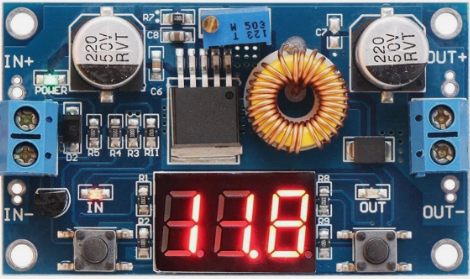
A Buck Converter is a type of DC-DC converter that steps down voltage while stepping up current. It uses a switching element, typically a transistor, along with an inductor, diode, and capacitor to efficiently convert a higher input voltage to a lower output voltage. Buck converters are widely used in power supply systems due to their high efficiency and compact design.
Explore Projects Built with Buck Convertor


Explore Projects Built with Buck Convertor
Common Applications and Use Cases
- Powering low-voltage devices from higher-voltage sources (e.g., 12V to 5V conversion)
- Battery-powered systems to regulate voltage
- LED drivers and lighting systems
- Embedded systems and microcontrollers
- Renewable energy systems (e.g., solar charge controllers)
Technical Specifications
Below are the general technical specifications for a typical Buck Converter. Note that specific values may vary depending on the model and manufacturer.
Key Technical Details
| Parameter | Typical Range/Value |
|---|---|
| Input Voltage Range | 4.5V to 40V |
| Output Voltage Range | 0.8V to 36V (adjustable in some models) |
| Output Current | Up to 10A (depending on the design) |
| Efficiency | Up to 95% |
| Switching Frequency | 100 kHz to 1 MHz |
| Operating Temperature | -40°C to +85°C |
Pin Configuration and Descriptions
| Pin Name | Description |
|---|---|
| VIN | Input voltage pin. Connect the higher input voltage here. |
| GND | Ground pin. Connect to the ground of the circuit. |
| VOUT | Output voltage pin. Provides the stepped-down voltage. |
| EN (Enable) | Enable pin. Used to turn the converter on or off (optional in some models). |
| FB (Feedback) | Feedback pin. Used to regulate the output voltage (optional in some models). |
Usage Instructions
How to Use the Buck Converter in a Circuit
Connect the Input Voltage (VIN):
- Connect the positive terminal of the input voltage source to the VIN pin.
- Connect the negative terminal of the input voltage source to the GND pin.
Connect the Output Load:
- Connect the positive terminal of the load to the VOUT pin.
- Connect the negative terminal of the load to the GND pin.
Adjust the Output Voltage (if adjustable):
- Use the onboard potentiometer (if available) to set the desired output voltage.
- Measure the output voltage using a multimeter to ensure accuracy.
Enable the Converter (if applicable):
- If the Buck Converter has an EN (Enable) pin, connect it to a HIGH signal (e.g., 5V) to turn it on.
- To disable the converter, connect the EN pin to GND.
Add External Components (if required):
- Some Buck Converters may require external capacitors or inductors for optimal performance. Refer to the datasheet for specific recommendations.
Important Considerations and Best Practices
- Input Voltage Range: Ensure the input voltage is within the specified range to avoid damaging the converter.
- Heat Dissipation: Buck Converters can generate heat during operation. Use a heatsink or ensure proper ventilation if necessary.
- Load Current: Do not exceed the maximum output current rating to prevent overheating or failure.
- Ripple Voltage: Use appropriate capacitors to minimize output voltage ripple.
- Inductor Selection: If using a custom design, choose an inductor with the correct inductance and current rating.
Example: Using a Buck Converter with Arduino UNO
Below is an example of how to use a Buck Converter to power an Arduino UNO from a 12V source.
Circuit Connections
- Connect the 12V input source to the VIN and GND pins of the Buck Converter.
- Adjust the Buck Converter to output 5V using the onboard potentiometer.
- Connect the 5V output of the Buck Converter to the 5V pin of the Arduino UNO.
- Connect the GND pin of the Buck Converter to the GND pin of the Arduino UNO.
Sample Code
// Example code to blink an LED using Arduino UNO powered by a Buck Converter

const int ledPin = 13; // Pin connected to the onboard LED

void setup() {
  pinMode(ledPin, OUTPUT); // Set the LED pin as an output
}

void loop() {
  digitalWrite(ledPin, HIGH); // Turn the LED on
  delay(1000);               // Wait for 1 second
  digitalWrite(ledPin, LOW);  // Turn the LED off
  delay(1000);               // Wait for 1 second
}
Troubleshooting and FAQs
Common Issues and Solutions
No Output Voltage:
- Check the input voltage and ensure it is within the specified range.
- Verify all connections, especially VIN, GND, and VOUT.
- If the converter has an EN pin, ensure it is connected to a HIGH signal.
Overheating:
- Ensure the load current does not exceed the maximum rating.
- Use a heatsink or improve ventilation around the converter.
Output Voltage Not Stable:
- Check for proper capacitor placement and values.
- Verify the inductor is correctly rated for the application.
High Ripple Voltage:
- Add low ESR capacitors to the output.
- Ensure the switching frequency is appropriate for the application.
FAQs
Q: Can I use a Buck Converter to power a microcontroller directly?
A: Yes, as long as the output voltage and current of the Buck Converter match the requirements of the microcontroller.
Q: What happens if I exceed the input voltage range?
A: Exceeding the input voltage range can damage the Buck Converter. Always ensure the input voltage is within the specified range.
Q: How do I calculate the required inductor value for a custom Buck Converter design?
A: The inductor value depends on the input voltage, output voltage, switching frequency, and load current. Use the formula provided in the datasheet or design guidelines for your specific IC.
Q: Can I use a Buck Converter for AC voltage?
A: No, Buck Converters are designed for DC input only. Use an AC-DC converter to first rectify and filter the AC voltage.