How to Use Arcade Button (yellow): Examples, Pinouts, and Specs
Introduction
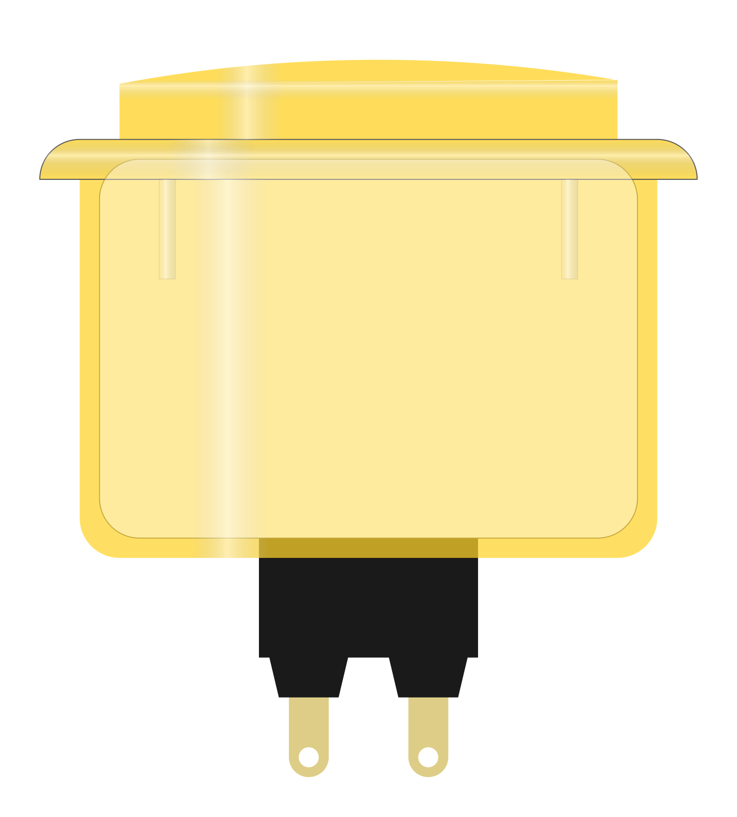
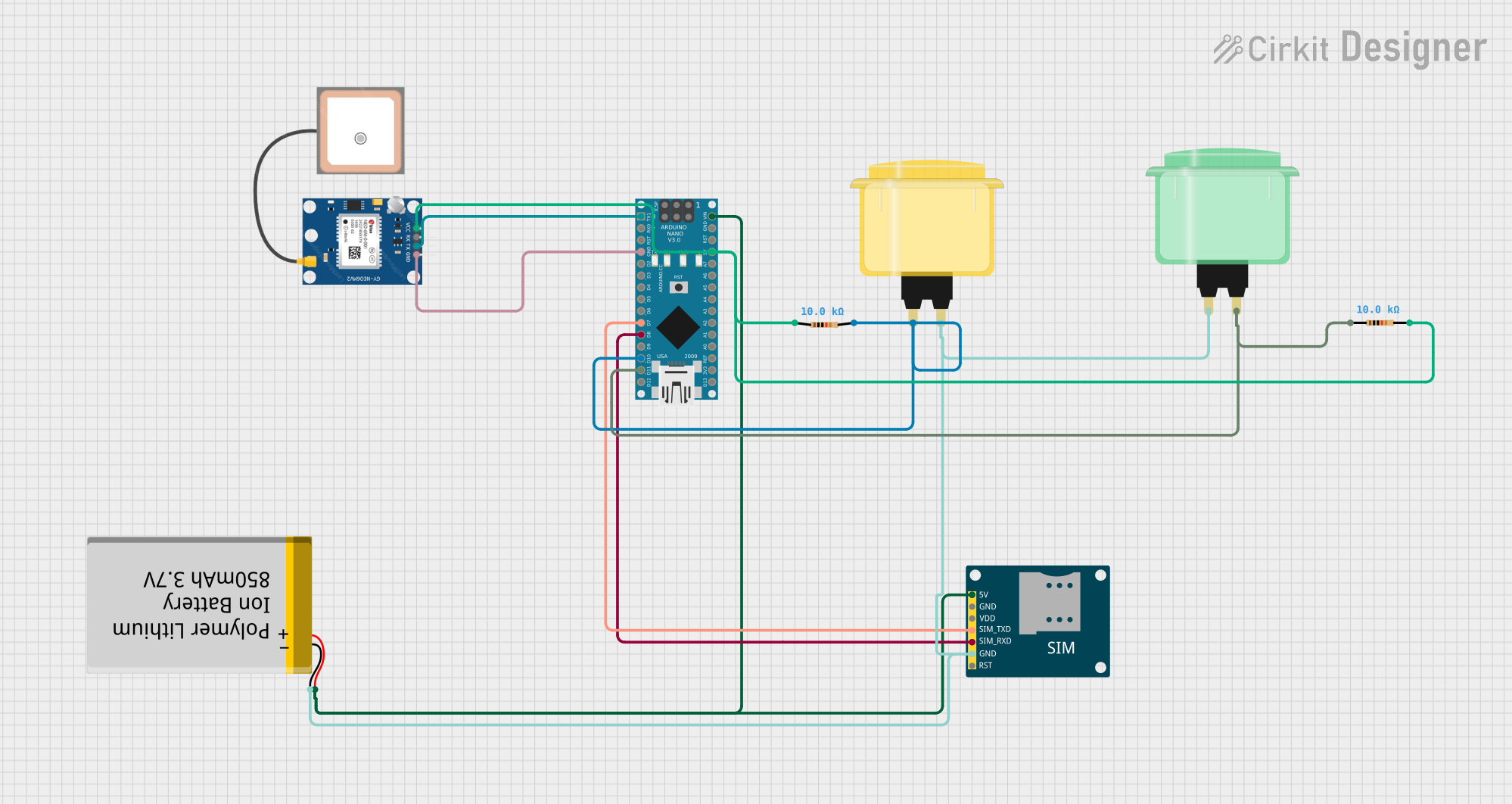
The Arcade Button (yellow) is a momentary push button that offers a classic arcade game feel to any project. It is designed for high-traffic use, capable of withstanding repeated presses without failure. The button's bright yellow color makes it easily identifiable, and its tactile feedback is both satisfying and reliable. Common applications include arcade machine controls, DIY game controllers, interactive art installations, and educational projects where user input is required.
Explore Projects Built with Arcade Button (yellow)
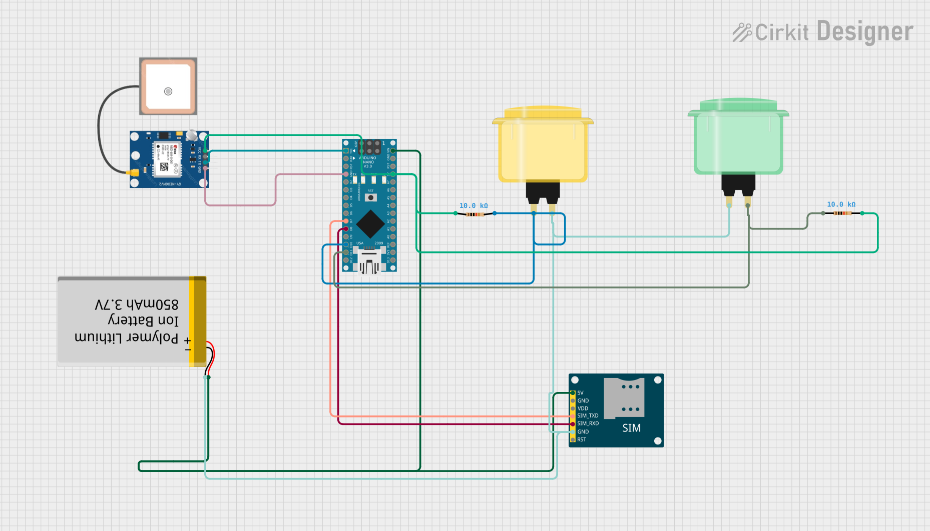
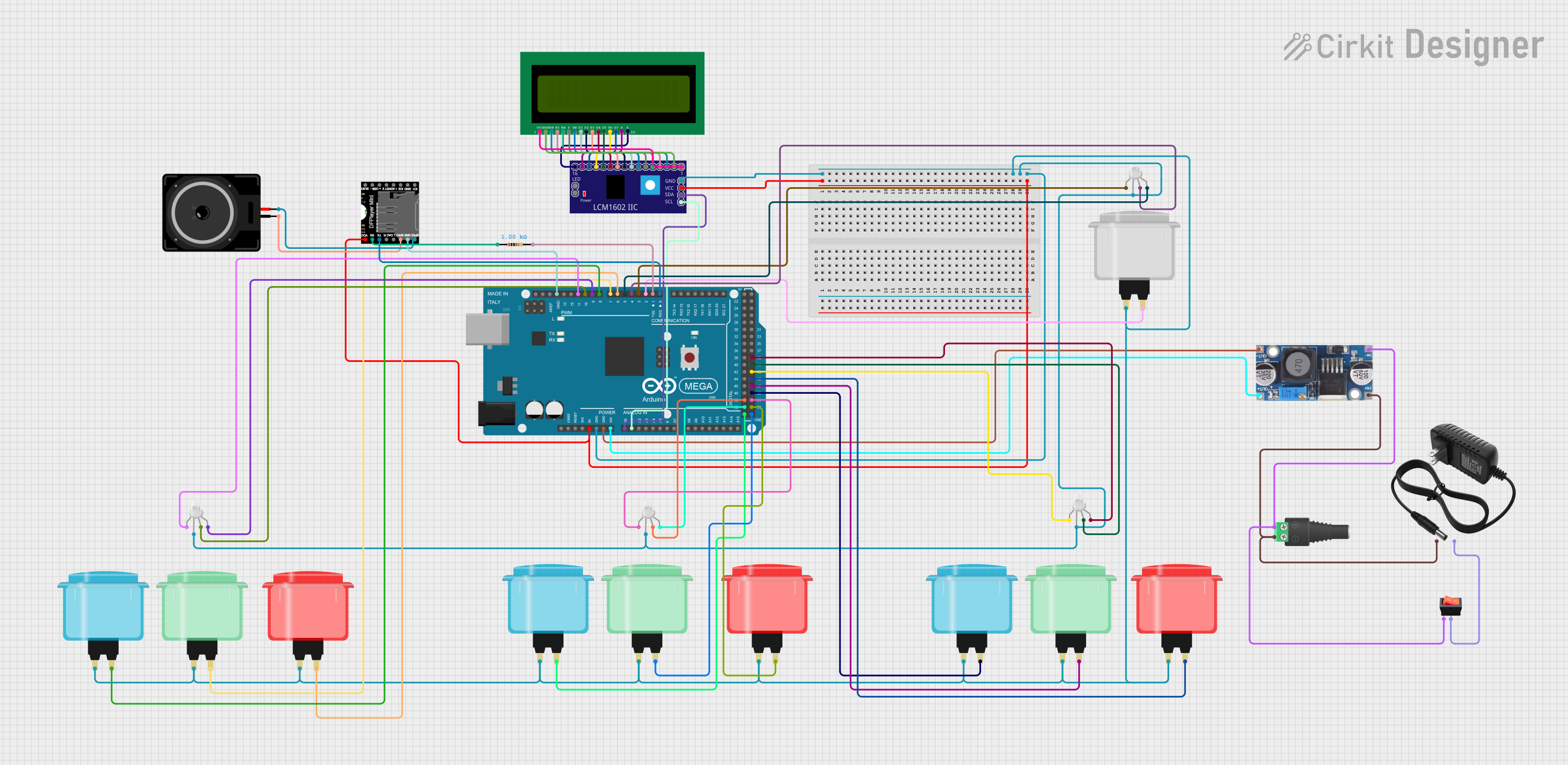
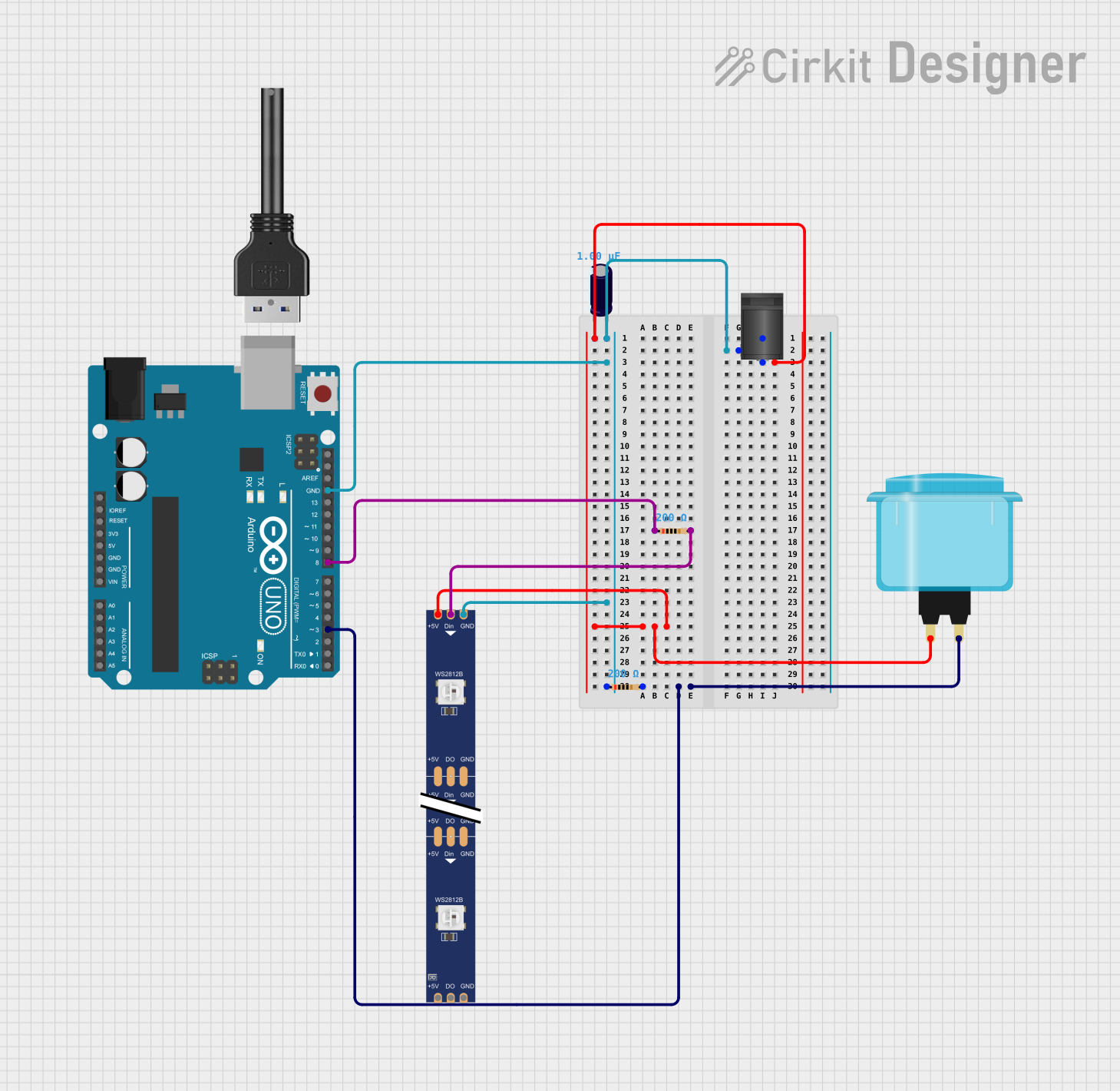
Explore Projects Built with Arcade Button (yellow)
Technical Specifications
Key Technical Details
- Switch Type: Momentary push button
- Color: Yellow
- Material: Durable plastic
- Contact Type: Normally open (NO)
- Mounting Hole Diameter: Typically 28-30mm
- Voltage Rating: Up to 250V AC
- Current Rating: Up to 10A
- Contact Resistance: <50 mΩ
- Insulation Resistance: >100 MΩ
- Operating Temperature: -10°C to +70°C
Pin Configuration and Descriptions
| Pin Number | Description |
|---|---|
| 1 | Common (COM) |
| 2 | Normally Open (NO) |
Usage Instructions
How to Use the Component in a Circuit
- Mounting the Button: Drill a hole with the appropriate diameter on your panel and secure the button in place.
- Wiring: Connect the COM pin to one side of your power source or signal line. The NO pin should be connected to the input you wish to control, such as an Arduino digital pin for signal input or another line for power control.
- Activation: When the button is pressed, the circuit between the COM and NO pins will close, allowing current to flow and sending a signal to your control system.
Important Considerations and Best Practices
- Debounce: Mechanical buttons like the Arcade Button can produce noisy signals when pressed or released. Implement software debouncing or use a hardware debounce circuit to ensure clean signal transitions.
- Load Rating: Do not exceed the voltage and current ratings of the button to prevent damage.
- Environment: While durable, the button should not be exposed to liquids or corrosive substances that could damage its components.
Example Code for Arduino UNO
// Define the pin connected to the Arcade Button
const int buttonPin = 2;
// Variable for reading the button status
int buttonState = 0;

void setup() {
  // Initialize the button pin as an input
  pinMode(buttonPin, INPUT);
}

void loop(){
  // Read the state of the button value
  buttonState = digitalRead(buttonPin);

  // Check if the button is pressed
  if (buttonState == HIGH) {
    // The button is pressed; perform an action
    // Note: HIGH means the button is NOT pressed in this configuration
  } else {
    // The button is not pressed; perform another action
  }
}
Troubleshooting and FAQs
Common Issues
- Button does not respond: Ensure the button is properly wired and the contacts are not damaged. Check for continuity with a multimeter.
- Intermittent or multiple signals: This is likely due to switch bounce. Implement a debounce algorithm in your code or use a debounce circuit.
Solutions and Tips for Troubleshooting
- Debounce Code: Implement a simple debounce by adding a delay after detecting a button press or use more sophisticated software debouncing techniques.
- Check Connections: Loose connections can cause unreliable button operation. Ensure all connections are secure.
- Test with Multimeter: Use a multimeter to test the continuity of the button when pressed. If there is no continuity, the button may be defective.
FAQs
Q: Can I use the Arcade Button with a microcontroller operating at 3.3V? A: Yes, the button is a mechanical switch and does not have a voltage requirement for the signal line.
Q: How do I know if my button press is being registered? A: You can use a simple LED circuit to visually indicate a button press or use serial output to monitor button state changes in your Arduino IDE.
Q: Is it necessary to use external pull-up or pull-down resistors? A: It depends on your circuit design. Many microcontrollers, like the Arduino, have internal pull-up resistors that can be enabled through software. If using external resistors, a 10kΩ resistor is commonly used.
Q: How can I customize the button for my project? A: You can add custom labels or replace the button cap with a different color or design to match your project's aesthetic.