How to Use piezoelectric: Examples, Pinouts, and Specs
Introduction
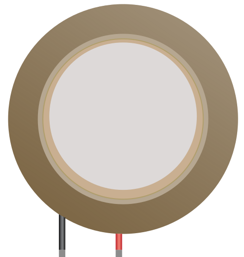
A piezoelectric component generates an electric charge in response to applied mechanical stress. This unique property makes it highly versatile and widely used in various applications. Commonly, piezoelectric components are found in sensors, actuators, and transducers. They are used to convert mechanical energy into electrical energy or vice versa, enabling functionalities such as sound generation, vibration sensing, and precise motion control.
Explore Projects Built with piezoelectric
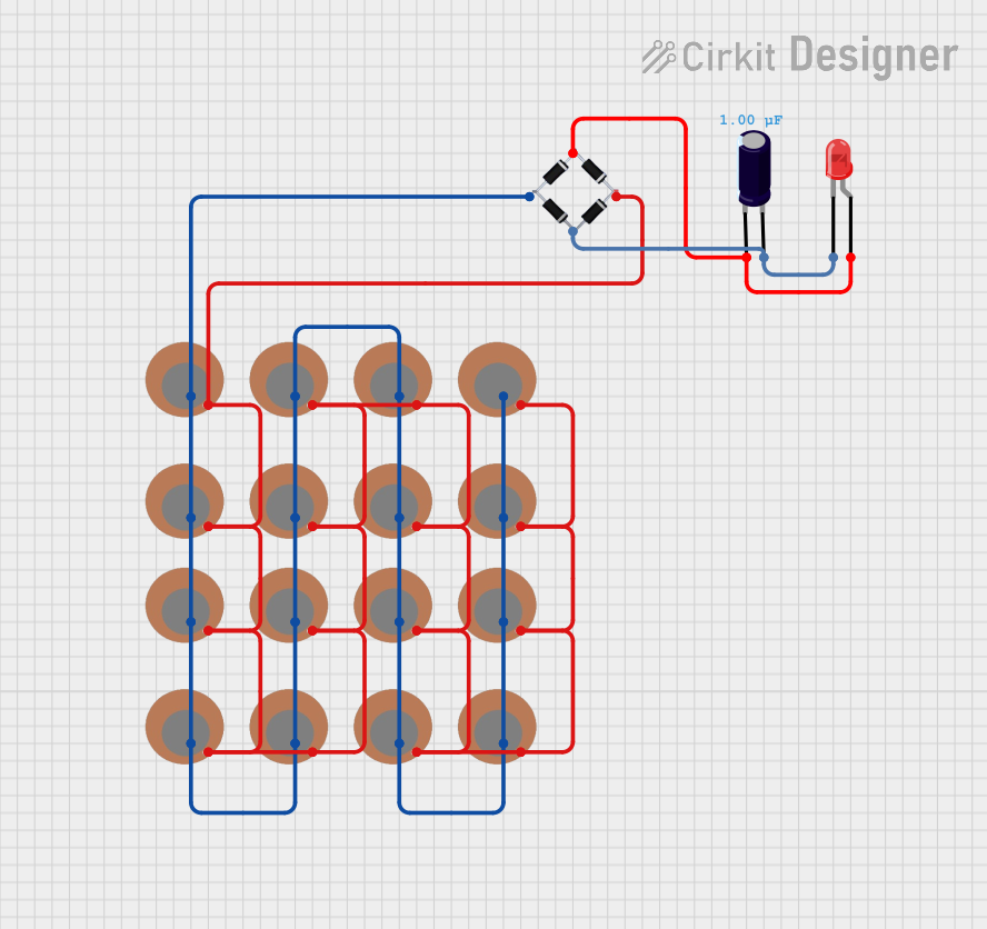
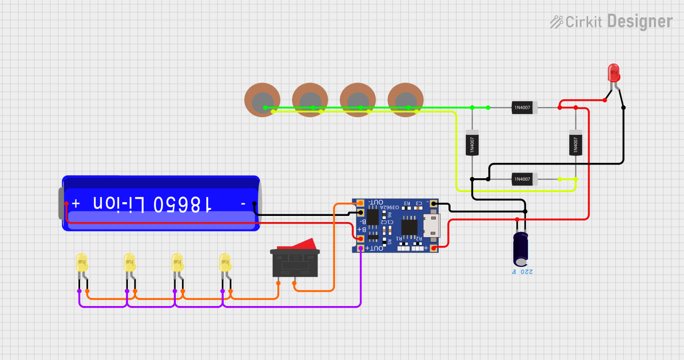
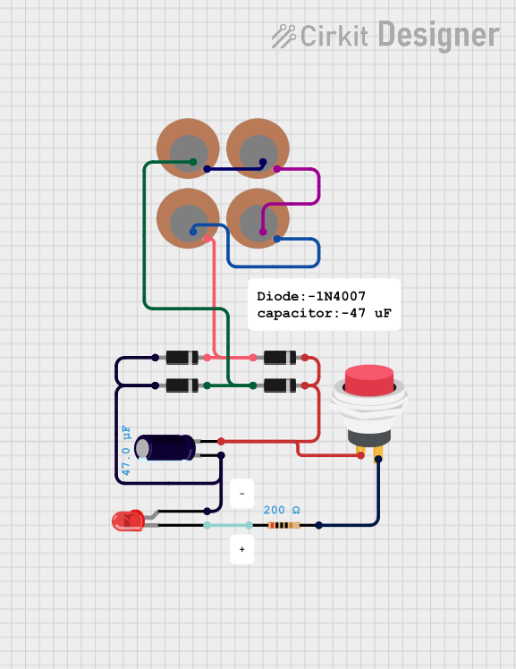
Explore Projects Built with piezoelectric
Common Applications:
- Buzzers and alarms: Used in electronic devices to produce sound.
- Vibration sensors: Detect mechanical vibrations in industrial and consumer applications.
- Ultrasonic transducers: Generate and detect ultrasonic waves for imaging or cleaning.
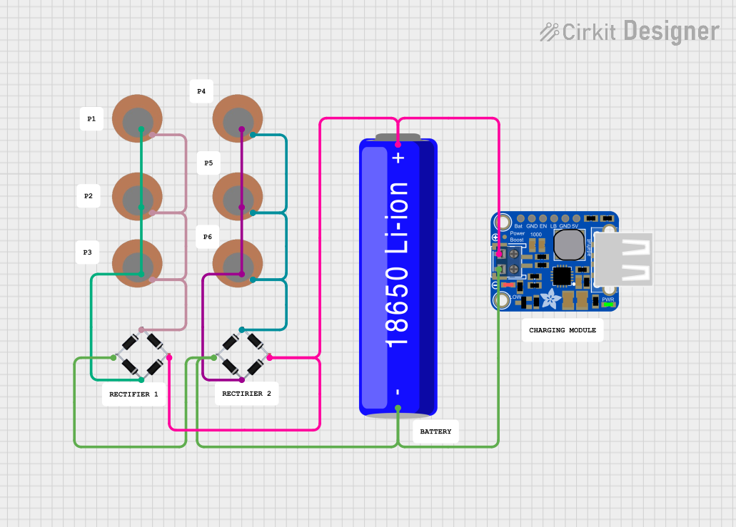
- Energy harvesting: Convert mechanical energy (e.g., vibrations) into electrical energy.
- Precision actuators: Enable fine motion control in robotics and medical devices.
Technical Specifications
The technical specifications of a piezoelectric component can vary depending on its type and application. Below are general specifications for a typical piezoelectric buzzer or sensor:
General Specifications:
| Parameter | Value |
|---|---|
| Operating Voltage | 3V to 12V (typical) |
| Resonant Frequency | 2 kHz to 10 kHz (varies by model) |
| Current Consumption | 5 mA to 30 mA (depends on usage) |
| Output Sound Pressure | 80 dB to 100 dB (at 10 cm) |
| Operating Temperature | -20°C to +70°C |
| Dimensions | Varies (e.g., 10 mm to 50 mm) |
Pin Configuration:
For a typical piezoelectric buzzer or sensor, the pin configuration is as follows:
| Pin | Name | Description |
|---|---|---|
| 1 | Positive (+) | Connect to the positive terminal of the power supply. |
| 2 | Negative (-) | Connect to ground (GND). |
Usage Instructions
How to Use a Piezoelectric Component in a Circuit:
- Power Supply: Connect the positive pin of the piezoelectric component to a voltage source (e.g., 5V) and the negative pin to ground.
- Driving Circuit: For buzzers, use a microcontroller or oscillator circuit to generate a square wave signal at the resonant frequency of the component.
- Sensor Applications: When used as a sensor, connect the piezoelectric component to an amplifier circuit to detect the small voltage generated by mechanical stress.
Example: Connecting a Piezoelectric Buzzer to an Arduino UNO
Below is an example of how to connect and control a piezoelectric buzzer using an Arduino UNO:
Circuit Diagram:
- Connect the positive pin of the buzzer to Arduino pin 9.
- Connect the negative pin of the buzzer to GND.
Arduino Code:
// Piezoelectric Buzzer Example with Arduino UNO
// This code generates a tone on the buzzer connected to pin 9.

#define BUZZER_PIN 9  // Define the pin connected to the buzzer

void setup() {
  pinMode(BUZZER_PIN, OUTPUT);  // Set the buzzer pin as an output
}

void loop() {
  tone(BUZZER_PIN, 1000);  // Generate a 1 kHz tone on the buzzer
  delay(500);              // Wait for 500 ms
  noTone(BUZZER_PIN);      // Stop the tone
  delay(500);              // Wait for 500 ms
}
Important Considerations:
- Frequency Matching: Ensure the driving frequency matches the resonant frequency of the piezoelectric component for optimal performance.
- Voltage Limits: Do not exceed the maximum operating voltage to avoid damaging the component.
- Mounting: For sensors, ensure proper mechanical coupling to the surface to detect vibrations effectively.
Troubleshooting and FAQs
Common Issues and Solutions:
No Sound from the Buzzer:
- Cause: Incorrect wiring or insufficient voltage.
- Solution: Verify the connections and ensure the power supply meets the component's requirements.
Low Sound Output:
- Cause: Driving frequency does not match the resonant frequency.
- Solution: Adjust the frequency of the driving signal to match the component's specifications.
No Signal from the Sensor:
- Cause: Weak mechanical coupling or insufficient stress applied.
- Solution: Ensure the sensor is securely mounted and subjected to adequate mechanical stress.
Overheating:
- Cause: Exceeding the voltage or current rating.
- Solution: Use a regulated power supply and check the component's ratings.
FAQs:
Q: Can I use a piezoelectric buzzer without a microcontroller?
A: Yes, you can use an oscillator circuit (e.g., a 555 timer) to drive the buzzer.Q: How do I amplify the signal from a piezoelectric sensor?
A: Use an operational amplifier (op-amp) circuit to boost the small voltage generated by the sensor.Q: Can piezoelectric components be used for energy harvesting?
A: Yes, they can convert mechanical vibrations into electrical energy, but the output is typically low and may require a power management circuit.
By following this documentation, you can effectively use piezoelectric components in your projects and troubleshoot common issues.