
How to Use ic: Examples, Pinouts, and Specs
 Design with ic in Cirkit Designer
Introduction
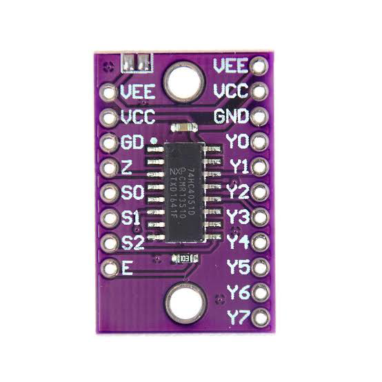
An integrated circuit (IC) is a miniaturized electronic circuit that combines multiple components such as transistors, resistors, and capacitors into a single chip. ICs are designed to perform a wide range of functions, from simple logic operations to complex signal processing. Their compact size, reliability, and efficiency make them a cornerstone of modern electronics.
Explore Projects Built with ic
 Open Project in Cirkit Designer
 Open Project in Cirkit Designer
 Open Project in Cirkit Designer
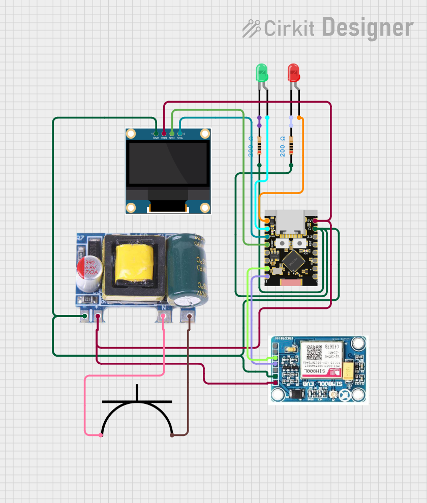 Open Project in Cirkit Designer
Explore Projects Built with ic
Open Project in Cirkit DesignerOpen Project in Cirkit DesignerOpen Project in Cirkit DesignerOpen Project in Cirkit DesignerCommon Applications and Use Cases
- Consumer Electronics: Found in smartphones, televisions, and computers.
- Automotive Systems: Used in engine control units, infotainment systems, and sensors.
- Industrial Automation: Powering control systems, robotics, and monitoring devices.
- Medical Devices: Enabling compact and efficient diagnostic and monitoring equipment.
- Communication Systems: Used in radios, modems, and networking devices.
Technical Specifications
ICs come in a variety of types, each with unique specifications. Below is an example of a general-purpose IC, such as the 555 Timer IC, to illustrate typical specifications.
Key Technical Details
- Supply Voltage (Vcc): 4.5V to 15V
- Operating Temperature: -40°C to 125°C
- Output Current: Up to 200mA
- Power Dissipation: 600mW (typical)
- Package Types: DIP, SOIC, QFN, etc.
Pin Configuration and Descriptions
Below is the pin configuration for a 555 Timer IC in an 8-pin Dual In-line Package (DIP):
| Pin Number | Pin Name | Description |
|---|---|---|
| 1 | GND | Ground pin, connected to the negative terminal of the power supply. |
| 2 | TRIG | Trigger input, starts the timing interval when voltage drops below 1/3 Vcc. |
| 3 | OUT | Output pin, provides the output signal. |
| 4 | RESET | Resets the timing interval when connected to ground. |
| 5 | CTRL | Control voltage, used to adjust the threshold voltage. |
| 6 | THR | Threshold input, ends the timing interval when voltage exceeds 2/3 Vcc. |
| 7 | DISCH | Discharge pin, connected to the timing capacitor. |
| 8 | VCC | Positive power supply pin. |
Usage Instructions
How to Use the Component in a Circuit
- Power Supply: Connect the VCC pin to a stable power source within the specified voltage range, and the GND pin to ground.
- Input Signals: Provide appropriate input signals to the TRIG and other input pins based on the IC's function.
- Output: Connect the OUT pin to the desired load or circuit.
- External Components: Use resistors, capacitors, or other components as specified in the IC's datasheet to configure its operation.
Example: 555 Timer in Astable Mode
The 555 Timer IC can be used to generate a square wave. Below is an example circuit and Arduino code to demonstrate its use.
Circuit Description
- Connect a 10kΩ resistor between VCC and pin 7 (DISCH).
- Connect a 100kΩ resistor between pin 7 (DISCH) and pin 6 (THR).
- Connect a 10µF capacitor between pin 6 (THR) and GND.
- Connect pin 2 (TRIG) to pin 6 (THR).
- Connect pin 3 (OUT) to an LED with a 220Ω resistor in series.
Arduino Code Example
// This code demonstrates how to use a 555 Timer IC to generate a square wave
// and control an LED using an Arduino UNO.

const int ledPin = 3; // Pin connected to the 555 Timer's OUT pin

void setup() {
  pinMode(ledPin, OUTPUT); // Set the LED pin as an output
}

void loop() {
  digitalWrite(ledPin, HIGH); // Turn the LED on
  delay(500);                // Wait for 500ms
  digitalWrite(ledPin, LOW);  // Turn the LED off
  delay(500);                // Wait for 500ms
}
Important Considerations and Best Practices
- Power Supply Stability: Ensure the power supply voltage is within the IC's specified range to avoid damage.
- Heat Dissipation: Use proper heat sinks or cooling mechanisms if the IC generates significant heat.
- Decoupling Capacitors: Place decoupling capacitors near the IC's power pins to reduce noise and improve stability.
- Static Sensitivity: Handle ICs with care to avoid damage from electrostatic discharge (ESD).
Troubleshooting and FAQs
Common Issues
No Output Signal:
- Check the power supply connections and ensure the IC is receiving the correct voltage.
- Verify that all external components are connected as per the circuit diagram.
Overheating:
- Ensure the IC is not exceeding its maximum power dissipation rating.
- Check for short circuits or incorrect connections.
Unstable Operation:
- Add decoupling capacitors near the power supply pins.
- Verify the values of external resistors and capacitors.
FAQs
Q: Can I use an IC with a higher supply voltage than specified?
A: No, exceeding the maximum supply voltage can permanently damage the IC.
Q: How do I identify the pin numbers on an IC?
A: Look for a small dot or notch on the IC package. Pin 1 is typically located next to this mark.
Q: Can I use a 555 Timer IC for PWM generation?
A: Yes, the 555 Timer IC can be configured in astable mode to generate a PWM signal by adjusting the resistor and capacitor values.
By following this documentation, users can effectively integrate ICs into their projects and troubleshoot common issues.