How to Use Switch: Examples, Pinouts, and Specs
Introduction
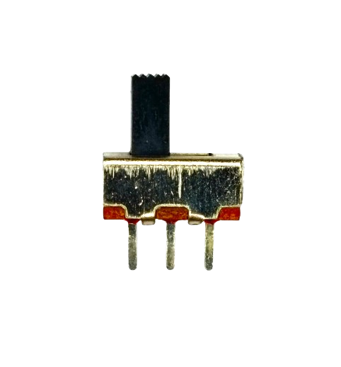
A switch is an electrical component that can open or close a circuit, allowing or interrupting the flow of current. It is one of the most fundamental components in electronics, used to control the operation of devices by manually or automatically toggling the flow of electricity. Switches come in various types, such as toggle switches, push-button switches, slide switches, and rotary switches, each suited for specific applications.
Explore Projects Built with Switch


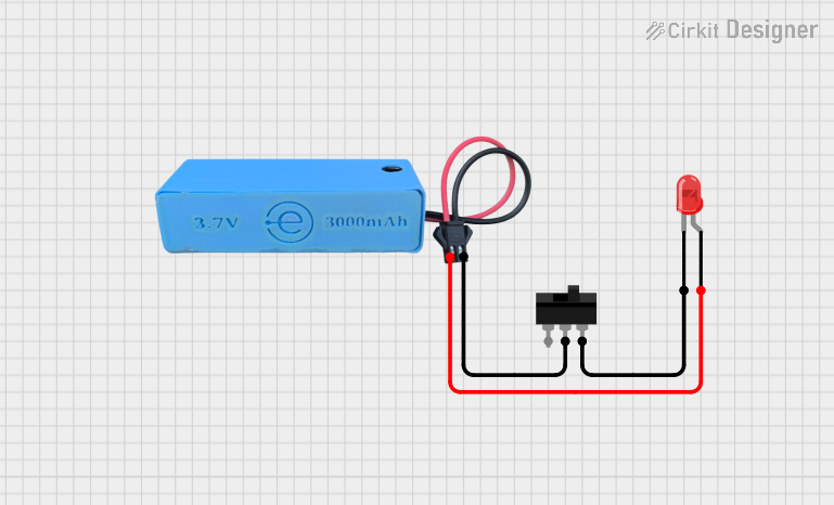

Explore Projects Built with Switch
Common Applications and Use Cases
- Turning devices on or off (e.g., lights, fans, appliances)
- Mode selection in electronic devices
- Reset buttons in circuits
- User input in embedded systems
- Safety mechanisms to disconnect power in emergencies
Technical Specifications
Switches vary widely in their specifications depending on the type and intended application. Below are general specifications for a typical mechanical switch:
| Parameter | Value |
|---|---|
| Voltage Rating | 3V to 250V (AC or DC, depending on type) |
| Current Rating | 0.1A to 15A (varies by model) |
| Contact Resistance | < 50 mΩ |
| Insulation Resistance | > 100 MΩ |
| Mechanical Lifespan | 10,000 to 1,000,000 operations |
| Operating Temperature | -20°C to 85°C |
Pin Configuration and Descriptions
The pin configuration of a switch depends on its type. Below is an example for a Single Pole Single Throw (SPST) switch:
| Pin Name | Description |
|---|---|
| Pin 1 | Input terminal for the circuit |
| Pin 2 | Output terminal for the circuit |
For a Double Pole Double Throw (DPDT) switch, the pin configuration is as follows:
| Pin Name | Description |
|---|---|
| Pin 1 | Input terminal for pole 1 |
| Pin 2 | Output terminal 1 for pole 1 |
| Pin 3 | Output terminal 2 for pole 1 |
| Pin 4 | Input terminal for pole 2 |
| Pin 5 | Output terminal 1 for pole 2 |
| Pin 6 | Output terminal 2 for pole 2 |
Usage Instructions
How to Use a Switch in a Circuit
- Identify the Type of Switch: Determine whether the switch is SPST, SPDT, DPDT, etc., as this affects how it is wired.
- Connect the Terminals:
- For an SPST switch, connect one terminal to the power source and the other to the load.
- For more complex switches like DPDT, refer to the pin configuration table above.
- Ensure Proper Ratings: Verify that the switch's voltage and current ratings match the circuit requirements.
- Test the Circuit: Toggle the switch to ensure it properly opens and closes the circuit.
Important Considerations and Best Practices
- Debouncing: Mechanical switches may produce noise or "bouncing" when toggled. Use a capacitor or software debouncing techniques in microcontroller circuits.
- Avoid Overloading: Ensure the switch is not subjected to voltages or currents beyond its rated capacity.
- Secure Connections: Use soldering or reliable connectors to prevent loose connections.
- Safety: Always disconnect power before wiring or modifying the switch in a circuit.
Example: Using a Switch with an Arduino UNO
Below is an example of how to use a push-button switch with an Arduino UNO to toggle an LED:
// Define pin numbers
const int switchPin = 2;  // Pin connected to the switch
const int ledPin = 13;    // Pin connected to the LED

// Variable to store the LED state
bool ledState = false;

void setup() {
  pinMode(switchPin, INPUT_PULLUP); // Set switch pin as input with pull-up resistor
  pinMode(ledPin, OUTPUT);          // Set LED pin as output
}

void loop() {
  // Check if the switch is pressed (LOW due to pull-up resistor)
  if (digitalRead(switchPin) == LOW) {
    delay(50); // Debounce delay
    if (digitalRead(switchPin) == LOW) { // Confirm switch press
      ledState = !ledState; // Toggle LED state
      digitalWrite(ledPin, ledState); // Update LED
      while (digitalRead(switchPin) == LOW); // Wait for switch release
    }
  }
}
Troubleshooting and FAQs
Common Issues
Switch Not Working:
- Cause: Loose connections or incorrect wiring.
- Solution: Double-check the wiring and ensure all connections are secure.
Switch Produces Erratic Behavior:
- Cause: Mechanical bouncing.
- Solution: Use a capacitor for hardware debouncing or implement software debouncing in your code.
Switch Overheats:
- Cause: Exceeding the current or voltage rating.
- Solution: Replace the switch with one that has a higher rating.
LED Does Not Toggle in Arduino Circuit:
- Cause: Incorrect pin configuration or faulty switch.
- Solution: Verify the pin numbers in the code and test the switch with a multimeter.
FAQs
Q: Can I use a switch to control high-power devices?
A: Yes, but ensure the switch is rated for the voltage and current of the device. For very high-power applications, consider using a relay controlled by the switch.
Q: What is the difference between SPST and SPDT switches?
A: SPST (Single Pole Single Throw) switches have one input and one output, while SPDT (Single Pole Double Throw) switches have one input and two outputs, allowing the circuit to toggle between two states.
Q: How do I debounce a switch in hardware?
A: Connect a small capacitor (e.g., 0.1 µF) across the switch terminals to filter out noise caused by bouncing.
Q: Can I use a switch with a microcontroller other than Arduino?
A: Yes, switches can be used with any microcontroller. The wiring and code logic will be similar, but pin configurations may vary.