How to Use DS2484 I2C to 1-Wire Bus Adapter Breakout: Examples, Pinouts, and Specs

 Design with DS2484 I2C to 1-Wire Bus Adapter Breakout in Cirkit Designer
Introduction
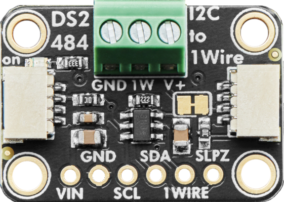
The DS2484 is a specialized interface designed to bridge the gap between an I2C bus and a 1-Wire network. Manufactured by Adafruit, this breakout board simplifies the integration of 1-Wire devices, such as temperature sensors, EEPROMs, and other peripherals, into microcontroller-based systems. By utilizing the DS2484, users can connect multiple 1-Wire devices to a microcontroller via the I2C protocol, reducing the complexity of direct 1-Wire communication.
Explore Projects Built with DS2484 I2C to 1-Wire Bus Adapter Breakout

 Open Project in Cirkit Designer
 Open Project in Cirkit Designer
 Open Project in Cirkit Designer
 Open Project in Cirkit Designer
Explore Projects Built with DS2484 I2C to 1-Wire Bus Adapter Breakout

 Open Project in Cirkit Designer
 Open Project in Cirkit Designer
 Open Project in Cirkit Designer
 Open Project in Cirkit Designer
Common Applications and Use Cases
- Temperature Monitoring: Interfacing with 1-Wire temperature sensors like the DS18B20.
- Data Logging: Connecting 1-Wire EEPROMs for data storage.
- Industrial Automation: Managing multiple 1-Wire devices in a robust and scalable manner.
- Home Automation: Integrating 1-Wire sensors for smart home applications.
Technical Specifications
The DS2484 breakout board is designed to provide reliable communication between I2C and 1-Wire devices. Below are its key technical details:
Key Technical Details
- I2C Voltage Range: 2.9V to 5.5V
- 1-Wire Voltage Range: 2.9V to 5.5V
- I2C Address: Configurable via jumpers (default:
0x18) - Operating Temperature: -40°C to +85°C
- Communication Protocols: I2C for host communication, 1-Wire for peripheral devices
- Pull-Up Resistors: Integrated 1-Wire pull-up resistor (can be disabled via jumper)
- Dimensions: Compact breakout board for easy integration
Pin Configuration and Descriptions
The DS2484 breakout board features the following pins:
| Pin Name | Type | Description |
|---|---|---|
| VIN | Power Input | Input voltage for the breakout board (2.9V to 5.5V). |
| GND | Ground | Ground connection. |
| SDA | I2C Data Line | Serial data line for I2C communication. |
| SCL | I2C Clock Line | Serial clock line for I2C communication. |
| 1W | 1-Wire Bus | Connection to the 1-Wire network. |
| ADDR | Address Select | Configures the I2C address (default: 0x18). |
| INT | Interrupt | Optional interrupt pin for advanced applications (not required for basic use). |
Usage Instructions
The DS2484 breakout board is straightforward to use in a circuit. Follow the steps below to integrate it into your project:
Step 1: Wiring the DS2484
- Power the Board: Connect the
VINpin to a 3.3V or 5V power source and theGNDpin to ground. - I2C Connection: Connect the
SDAandSCLpins to the corresponding I2C pins on your microcontroller. - 1-Wire Connection: Attach the
1Wpin to your 1-Wire network. Ensure that all 1-Wire devices share a common ground with the DS2484. - Optional Address Configuration: If using multiple DS2484 devices, configure the I2C address by adjusting the
ADDRpin.
Step 2: Using the DS2484 with an Arduino UNO
The DS2484 is compatible with Arduino boards. Below is an example of how to use the DS2484 to read data from a 1-Wire temperature sensor (e.g., DS18B20).
Example Code
#include <Wire.h>
#include <OneWire.h>
#include <DS2484.h>

// Create an instance of the DS2484 library
DS2484 ds2484;

// Define the 1-Wire bus pin (connected to the DS2484 breakout)
OneWire oneWire(10); // Pin 10 is used for the 1-Wire bus

void setup() {
  Serial.begin(9600);
  Wire.begin(); // Initialize I2C communication

  // Initialize the DS2484
  if (!ds2484.begin()) {
    Serial.println("Failed to initialize DS2484. Check connections.");
    while (1); // Halt execution if initialization fails
  }
  Serial.println("DS2484 initialized successfully.");

  // Initialize the 1-Wire bus
  oneWire.begin();
}

void loop() {
  byte addr[8];

  // Search for 1-Wire devices
  if (oneWire.search(addr)) {
    Serial.print("1-Wire device found: ");
    for (int i = 0; i < 8; i++) {
      Serial.print(addr[i], HEX);
      if (i < 7) Serial.print(":");
    }
    Serial.println();
  } else {
    Serial.println("No 1-Wire devices found.");
    oneWire.reset_search(); // Reset the search for the next loop
  }

  delay(1000); // Wait 1 second before the next search
}
Important Considerations and Best Practices
- Pull-Up Resistors: Ensure that the 1-Wire bus has a proper pull-up resistor (typically 4.7kΩ). The DS2484 breakout includes an integrated pull-up resistor, which can be disabled if an external resistor is preferred.
- I2C Address Conflicts: If using multiple I2C devices, ensure that each device has a unique address. Adjust the
ADDRpin on the DS2484 if necessary. - Power Supply: Verify that the power supply voltage matches the requirements of both the DS2484 and the connected 1-Wire devices.
Troubleshooting and FAQs
Common Issues and Solutions
DS2484 Not Detected on I2C Bus
- Cause: Incorrect wiring or I2C address conflict.
- Solution: Double-check the
SDAandSCLconnections. Ensure theADDRpin is configured correctly.
1-Wire Devices Not Responding
- Cause: Missing or incorrect pull-up resistor on the 1-Wire bus.
- Solution: Verify that the 1-Wire bus has a 4.7kΩ pull-up resistor. If using the DS2484's internal pull-up, ensure it is enabled.
Intermittent Communication Failures
- Cause: Noise or insufficient power supply.
- Solution: Use decoupling capacitors near the DS2484 and ensure a stable power source.
FAQs
Q: Can I use the DS2484 with a 3.3V microcontroller?
- A: Yes, the DS2484 supports both 3.3V and 5V logic levels.
Q: How many 1-Wire devices can I connect to the DS2484?
- A: The DS2484 supports multiple 1-Wire devices, but the exact number depends on the power supply and bus length.
Q: Is the DS2484 compatible with Raspberry Pi?
- A: Yes, the DS2484 can be used with Raspberry Pi via the I2C interface. Ensure proper I2C configuration on the Raspberry Pi.
By following this documentation, you can effectively integrate the DS2484 I2C to 1-Wire Bus Adapter Breakout into your projects for seamless communication with 1-Wire devices.