How to Use Servo Tutorial Component: Examples, Pinouts, and Specs
Introduction
The Servo Tutorial Component (Manufacturer: KunafaMan Co., Part ID: Kunafa Servo) is a versatile device designed to demonstrate and teach the principles of servo motors. This component is ideal for educational purposes, enabling users to understand servo motor control, positioning, and applications in robotics and automation. It is widely used in classrooms, workshops, and hobbyist projects to provide hands-on experience with servo motor technology.
Explore Projects Built with Servo Tutorial Component
Explore Projects Built with Servo Tutorial Component
Common Applications and Use Cases
- Educational demonstrations of servo motor principles
- Robotics and automation projects
- Prototyping and testing servo motor control systems
- Integration into Arduino-based projects for motion control
- DIY hobbyist projects requiring precise angular positioning
Technical Specifications
The Servo Tutorial Component is designed to be user-friendly and compatible with a wide range of microcontrollers, including Arduino boards. Below are the key technical details:
General Specifications
| Parameter | Value |
|---|---|
| Operating Voltage | 4.8V to 6.0V |
| Operating Current | 100mA to 250mA (typical) |
| Stall Current | ~1A |
| Torque | 1.8 kg·cm @ 4.8V, 2.2 kg·cm @ 6.0V |
| Operating Angle | 0° to 180° |
| Signal Type | PWM (Pulse Width Modulation) |
| PWM Pulse Range | 500µs to 2500µs |
| Weight | 9g |
| Dimensions | 22.5mm x 11.5mm x 24mm |
Pin Configuration
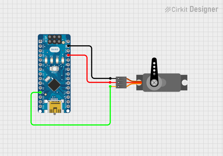
The Servo Tutorial Component has a standard 3-pin connector for easy integration into circuits. The pinout is as follows:
| Pin Number | Pin Name | Description |
|---|---|---|
| 1 | GND | Ground connection |
| 2 | VCC | Power supply (4.8V to 6.0V) |
| 3 | Signal | PWM control signal input |
Usage Instructions
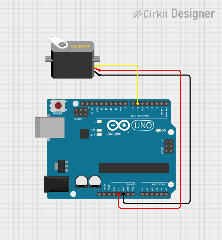
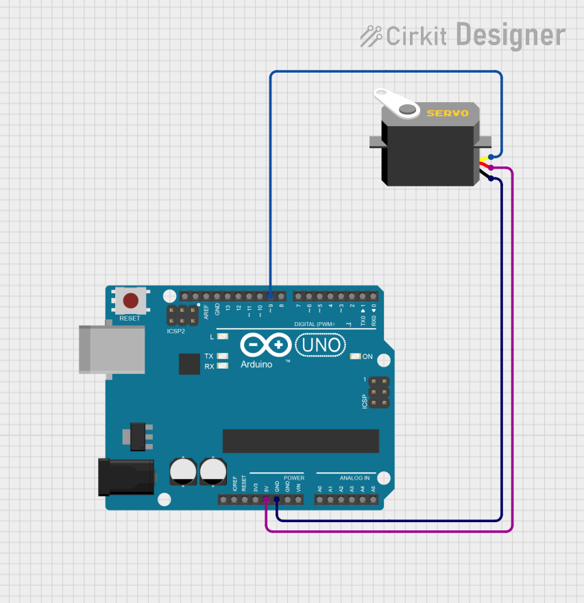
The Servo Tutorial Component is straightforward to use and can be controlled using a microcontroller like the Arduino UNO. Below are the steps to integrate and operate the servo:
Connecting the Servo
- Power Supply: Connect the VCC pin to a 5V power source and the GND pin to the ground of your circuit.
- Signal Input: Connect the Signal pin to a PWM-capable pin on your microcontroller (e.g., Pin 9 on an Arduino UNO).
- Load Considerations: Ensure the servo is not overloaded beyond its torque rating to avoid damage.
Arduino Example Code
The following example demonstrates how to control the Servo Tutorial Component using an Arduino UNO:
#include <Servo.h> // Include the Servo library

Servo myServo; // Create a Servo object to control the servo

void setup() {
  myServo.attach(9); // Attach the servo to pin 9 on the Arduino
}

void loop() {
  myServo.write(0); // Move the servo to 0 degrees
  delay(1000); // Wait for 1 second

  myServo.write(90); // Move the servo to 90 degrees
  delay(1000); // Wait for 1 second

  myServo.write(180); // Move the servo to 180 degrees
  delay(1000); // Wait for 1 second
}
Important Considerations
- Power Supply: Use a stable power source to avoid erratic servo behavior.
- PWM Signal: Ensure the PWM signal is within the specified range (500µs to 2500µs).
- Mechanical Load: Avoid applying excessive force or torque to the servo horn.
- Heat Management: Prolonged operation under high load may cause the servo to heat up. Allow it to cool if necessary.
Troubleshooting and FAQs
Common Issues and Solutions
Servo Not Moving
- Cause: Incorrect wiring or insufficient power supply.
- Solution: Verify the connections and ensure the power supply meets the voltage and current requirements.
Erratic Movement
- Cause: Unstable PWM signal or noisy power supply.
- Solution: Use a decoupling capacitor near the servo's power pins and ensure the PWM signal is clean.
Overheating
- Cause: Prolonged operation under high load or stalled motor.
- Solution: Reduce the load on the servo and avoid stalling the motor.
Limited Range of Motion
- Cause: PWM signal out of range or mechanical obstruction.
- Solution: Ensure the PWM signal is within the specified range and check for obstructions.
FAQs
Q: Can I use the Servo Tutorial Component with a 3.3V microcontroller?
A: Yes, but you must provide a separate 5V power supply for the servo, as it requires 4.8V to 6.0V for proper operation.
Q: What is the maximum weight the servo can lift?
A: The torque rating is 1.8 kg·cm at 4.8V and 2.2 kg·cm at 6.0V. Calculate the weight based on the distance from the servo horn's center.
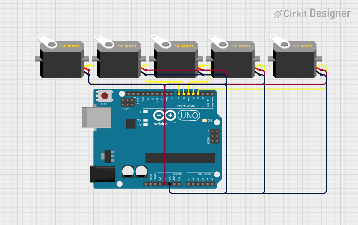
Q: Can I control multiple servos with one Arduino?
A: Yes, you can control multiple servos using different PWM-capable pins, but ensure the power supply can handle the combined current draw.
Q: How do I calibrate the servo?
A: Calibration is typically not required for this servo. However, ensure the PWM signal matches the specified range for accurate positioning.
This concludes the documentation for the Servo Tutorial Component by KunafaMan Co. For further assistance, refer to the manufacturer's support resources.