How to Use Vietduino Uno USB-C: Examples, Pinouts, and Specs
Introduction
The Vietduino Uno USB-C is a versatile microcontroller board developed by Makerlabvn. It is based on the ATmega328P microcontroller and is designed to be an easy-to-use platform for electronics enthusiasts, hobbyists, and professionals alike. The board is compatible with a wide range of shields and accessories, making it suitable for a variety of applications, from simple LED control to more complex robotics projects.
Common applications of the Vietduino Uno USB-C include:
- Prototyping and learning electronics and programming
- Building DIY projects and gadgets
- Creating interactive artworks
- Developing educational tools and kits
- Designing embedded systems
Explore Projects Built with Vietduino Uno USB-C
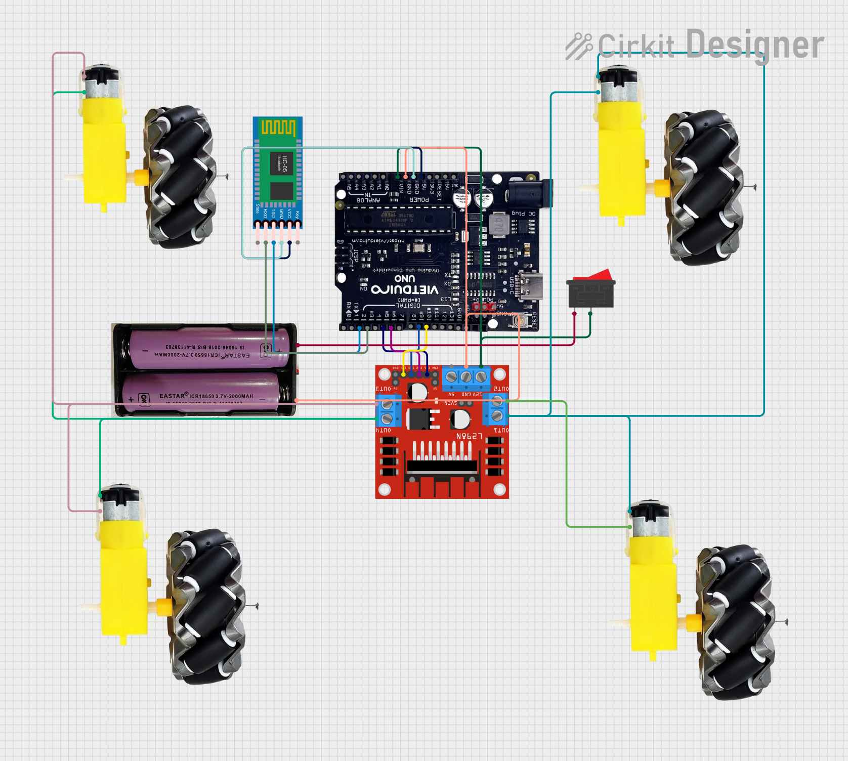
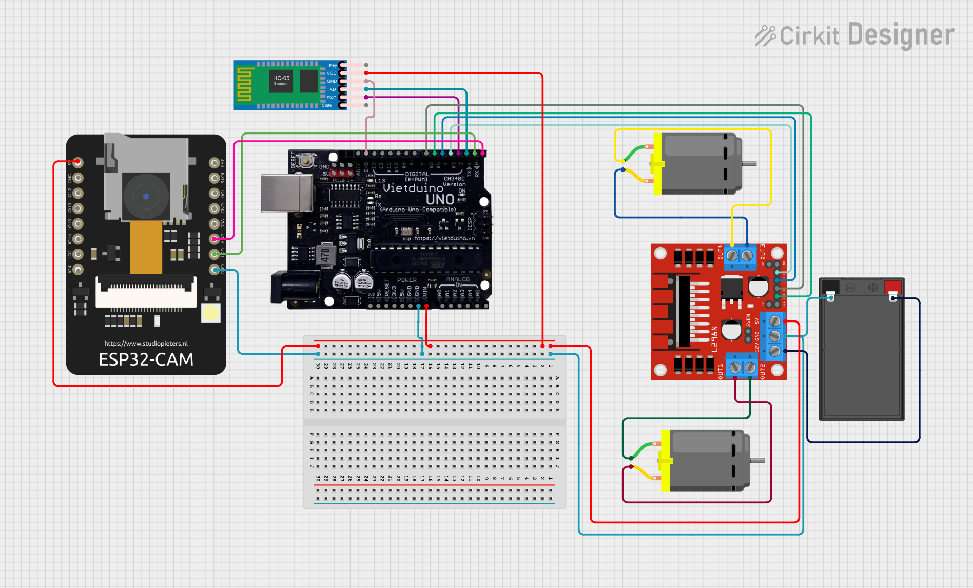
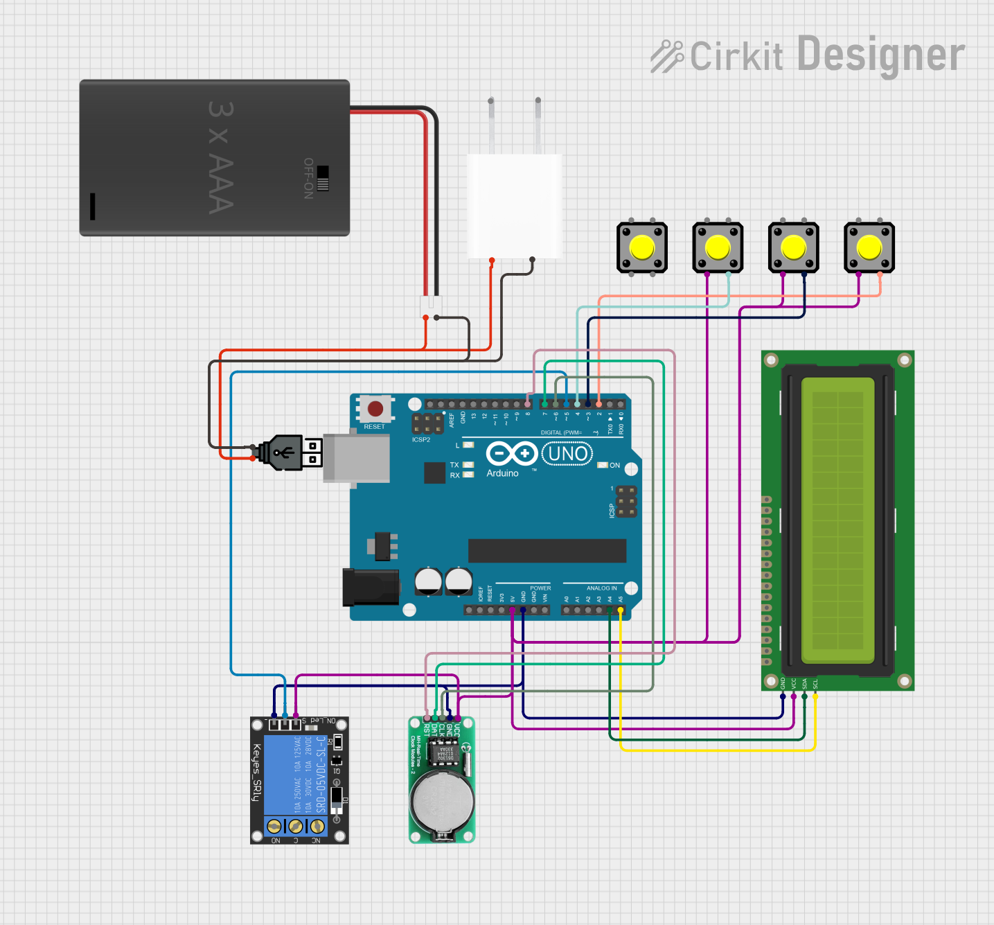
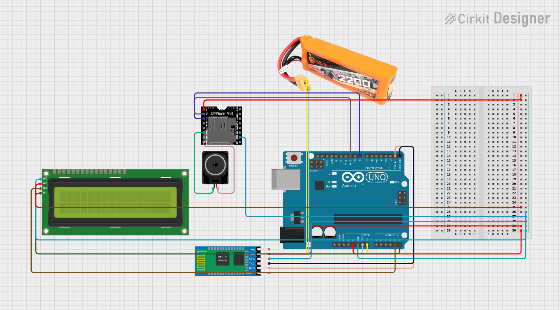
Explore Projects Built with Vietduino Uno USB-C
Technical Specifications
Key Technical Details
- Microcontroller: ATmega328P
- Operating Voltage: 5V
- Input Voltage (recommended): 7-12V
- Input Voltage (limit): 6-20V
- Digital I/O Pins: 14 (of which 6 provide PWM output)
- Analog Input Pins: 6
- DC Current per I/O Pin: 20 mA
- DC Current for 3.3V Pin: 50 mA
- Flash Memory: 32 KB (ATmega328P) of which 0.5 KB used by bootloader
- SRAM: 2 KB (ATmega328P)
- EEPROM: 1 KB (ATmega328P)
- Clock Speed: 16 MHz
- LED_BUILTIN: Pin 13
- USB Connection: USB-C
Pin Configuration and Descriptions
| Pin Number | Function | Description |
|---|---|---|
| 1 | RESET | Used to reset the microcontroller |
| 2-13 | Digital I/O | Digital pins, PWM available on pins 3, 5, 6, 9, 10, 11 |
| 14-19 | Analog Input | Analog input pins A0-A5 |
| 20 | AREF | Analog reference voltage for the ADC |
| 21 | GND | Ground |
| 22 | AREF | Analog reference voltage for the ADC |
| 23 | 3V3 | 3.3V output from the onboard regulator |
| 24 | D13/LED_BUILTIN | Digital pin 13 and built-in LED |
| 25 | SDA | I2C data line |
| 26 | SCL | I2C clock line |
| 27 | IOREF | This pin on the board provides the voltage reference |
| 28 | RESET | Another pin to reset the microcontroller |
| 29 | 3V3 | 3.3V output from the onboard regulator |
| 30 | 5V | Regulated 5V output |
| 31 | GND | Ground |
| 32 | GND | Ground |
| 33 | Vin | Input voltage to the board |
| 34 | 5V | Regulated 5V output |
| 35 | GND | Ground |
| 36 | GND | Ground |
| 37 | Vin | Input voltage to the board |
Usage Instructions
How to Use the Component in a Circuit
Powering the Board:
- You can power the Vietduino Uno USB-C via the USB-C connection or with an external power supply through the power jack. The recommended voltage range is 7-12V.
Connecting to a Computer:
- Connect the board to your computer using a USB-C cable to upload sketches and communicate with the board.
Writing a Sketch:
- Use the Arduino IDE or compatible software to write and upload your code to the Vietduino Uno USB-C.
Accessing I/O Pins:
- Utilize the digital and analog pins to interface with sensors, actuators, and other components.
Important Considerations and Best Practices
- Always disconnect the board from power sources before making or altering connections.
- Ensure that the voltage levels on the I/O pins do not exceed the specified limits to prevent damage.
- Use a current limiting resistor when connecting LEDs to the digital pins.
- Avoid drawing more than the maximum current from the 3.3V and 5V pins to prevent overheating and damage to the voltage regulator.
Troubleshooting and FAQs
Common Issues
- Board Not Recognized: Ensure that the USB-C cable is properly connected and that the drivers are installed.
- Sketch Not Uploading: Check the selected board and port in the Arduino IDE, and ensure the correct bootloader is used.
- Unexpected Behavior: Verify the wiring and components in your circuit, and check for code errors.
Solutions and Tips for Troubleshooting
- If the board is not recognized, try a different USB-C cable or port on your computer.
- For upload issues, double-check the board and processor settings in the Arduino IDE.
- Use the built-in LED on pin 13 to test basic functionality by uploading the Blink example sketch.
Example Code for Arduino UNO
Here is a simple example code that blinks the onboard LED:
// Pin 13 has an LED connected on most Arduino boards.
int led = 13;

// The setup routine runs once when you press reset:
void setup() {
  // Initialize the digital pin as an output.
  pinMode(led, OUTPUT);
}

// The loop routine runs over and over again forever:
void loop() {
  digitalWrite(led, HIGH);   // Turn the LED on (HIGH is the voltage level)
  delay(1000);               // Wait for a second
  digitalWrite(led, LOW);    // Turn the LED off by making the voltage LOW
  delay(1000);               // Wait for a second
}
Remember to select "Vietduino Uno USB-C" as your board when uploading this sketch if it is listed in the Arduino IDE, or select "Arduino/Genuino Uno" if it is not.
This documentation provides an overview of the Vietduino Uno USB-C board. For more detailed information, refer to the datasheets and resources provided by Makerlabvn.