Cirkit Designer Logo
Cirkit Designer
Your all-in-one circuit design IDE
Home / 
Component Documentation

How to Use DFRobot Tristimulus Color Sensor (v1.0): Examples, Pinouts, and Specs

Image of DFRobot Tristimulus Color Sensor (v1.0)
Cirkit Designer LogoDesign with DFRobot Tristimulus Color Sensor (v1.0) in Cirkit Designer

Introduction

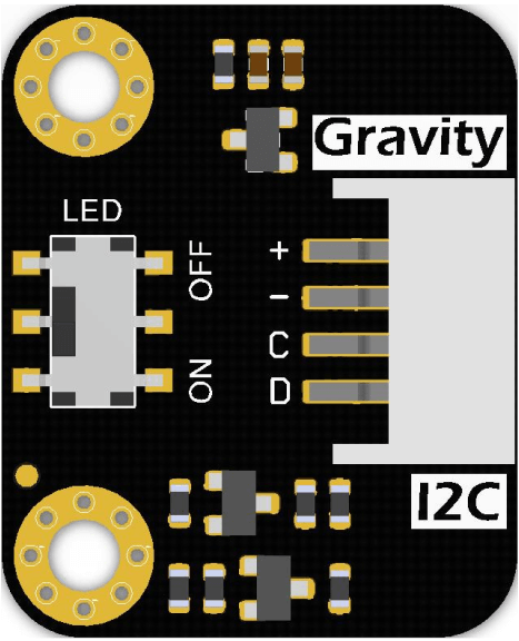
The DFRobot Tristimulus Color Sensor (v1.0), with the manufacturer part ID TCS3430, is an advanced electronic component designed to detect and measure the color of an object. It operates by analyzing the three primary colors of light – red, green, and blue (RGB) – and provides accurate color data. This sensor is ideal for a wide range of applications, including color matching, color sorting, ambient light sensing, and calibration in printing industries.

Explore Projects Built with DFRobot Tristimulus Color Sensor (v1.0)

Use Cirkit Designer to design, explore, and prototype these projects online. Some projects support real-time simulation. Click "Open Project" to start designing instantly!
Arduino UNO-Based Color Sorting Robot with Dual Servomotors and DC Motor Control
Image of colour sorting: A project utilizing DFRobot Tristimulus Color Sensor (v1.0) in a practical application
This circuit is a color-sensing robotic system controlled by an Arduino UNO. It uses a TCS3200 color sensor to detect colors and actuates two SG90 servomotors and a DC motor via an L298N motor driver based on the detected color. The system is powered by a Li-ion 18650 battery and is programmed to perform specific actions when red or green colors are detected.
Cirkit Designer LogoOpen Project in Cirkit Designer
Arduino UNO with TCS34725 Color Sensor and LDR Light Detection
Image of SSC: A project utilizing DFRobot Tristimulus Color Sensor (v1.0) in a practical application
This circuit features an Arduino UNO microcontroller connected to an Adafruit TCS34725 RGB Color Sensor and a photocell (LDR) with a 10k Ohm resistor forming a voltage divider connected to the Arduino's analog input A0. The RGB sensor is interfaced with the Arduino via I2C communication, using SDA and SCL lines. The purpose of this circuit is likely to measure ambient light intensity with the photocell and detect colors with the RGB sensor, both interfaced with the Arduino for processing and potential output of the sensor data.
Cirkit Designer LogoOpen Project in Cirkit Designer
Arduino-Based Robotic Arm with RGB Color Detection and Servo Control
Image of Adafruit: A project utilizing DFRobot Tristimulus Color Sensor (v1.0) in a practical application
This circuit is a color-sorting robotic arm controlled by an Arduino UNO. It uses an Adafruit TCS34725 RGB color sensor to detect the color of objects and four servos to manipulate and sort the objects based on their color. The system is powered by a 5V power supply and includes a pushbutton for user interaction.
Cirkit Designer LogoOpen Project in Cirkit Designer
Arduino Uno R3 and DFPlayer Mini-Based Interactive Color Sensor with Audio Feedback
Image of Educate shapes and colors for baby: A project utilizing DFRobot Tristimulus Color Sensor (v1.0) in a practical application
This circuit is a color and shape recognition system using an Arduino Uno, a TCS3472 color sensor, and multiple pushbuttons. It uses a DFPlayer Mini to play audio feedback based on the detected color or shape, with the audio output amplified by a PAM8403 module and played through a loudspeaker.
Cirkit Designer LogoOpen Project in Cirkit Designer

Explore Projects Built with DFRobot Tristimulus Color Sensor (v1.0)

Use Cirkit Designer to design, explore, and prototype these projects online. Some projects support real-time simulation. Click "Open Project" to start designing instantly!
Image of colour sorting: A project utilizing DFRobot Tristimulus Color Sensor (v1.0) in a practical application
Arduino UNO-Based Color Sorting Robot with Dual Servomotors and DC Motor Control
This circuit is a color-sensing robotic system controlled by an Arduino UNO. It uses a TCS3200 color sensor to detect colors and actuates two SG90 servomotors and a DC motor via an L298N motor driver based on the detected color. The system is powered by a Li-ion 18650 battery and is programmed to perform specific actions when red or green colors are detected.
Cirkit Designer LogoOpen Project in Cirkit Designer
Image of SSC: A project utilizing DFRobot Tristimulus Color Sensor (v1.0) in a practical application
Arduino UNO with TCS34725 Color Sensor and LDR Light Detection
This circuit features an Arduino UNO microcontroller connected to an Adafruit TCS34725 RGB Color Sensor and a photocell (LDR) with a 10k Ohm resistor forming a voltage divider connected to the Arduino's analog input A0. The RGB sensor is interfaced with the Arduino via I2C communication, using SDA and SCL lines. The purpose of this circuit is likely to measure ambient light intensity with the photocell and detect colors with the RGB sensor, both interfaced with the Arduino for processing and potential output of the sensor data.
Cirkit Designer LogoOpen Project in Cirkit Designer
Image of Adafruit: A project utilizing DFRobot Tristimulus Color Sensor (v1.0) in a practical application
Arduino-Based Robotic Arm with RGB Color Detection and Servo Control
This circuit is a color-sorting robotic arm controlled by an Arduino UNO. It uses an Adafruit TCS34725 RGB color sensor to detect the color of objects and four servos to manipulate and sort the objects based on their color. The system is powered by a 5V power supply and includes a pushbutton for user interaction.
Cirkit Designer LogoOpen Project in Cirkit Designer
Image of Educate shapes and colors for baby: A project utilizing DFRobot Tristimulus Color Sensor (v1.0) in a practical application
Arduino Uno R3 and DFPlayer Mini-Based Interactive Color Sensor with Audio Feedback
This circuit is a color and shape recognition system using an Arduino Uno, a TCS3472 color sensor, and multiple pushbuttons. It uses a DFPlayer Mini to play audio feedback based on the detected color or shape, with the audio output amplified by a PAM8403 module and played through a loudspeaker.
Cirkit Designer LogoOpen Project in Cirkit Designer

Technical Specifications

Key Technical Details

  • Supply Voltage (VDD): 2.7V to 3.6V
  • Maximum Supply Current: 5 mA
  • Operating Temperature Range: -30°C to 70°C
  • RGB Color Sensing: Integrated RGB filters
  • Interface: I2C
  • Sensitivity: Programmable
  • Output: 16-bit digital data for each color channel

Pin Configuration and Descriptions

Pin Number Pin Name Description
1 VDD Power supply (2.7V to 3.6V)
2 GND Ground
3 SCL Serial Clock Line for I2C communication
4 SDA Serial Data Line for I2C communication
5 INT Interrupt pin (active low)
6 ADDR I2C address select pin

Usage Instructions

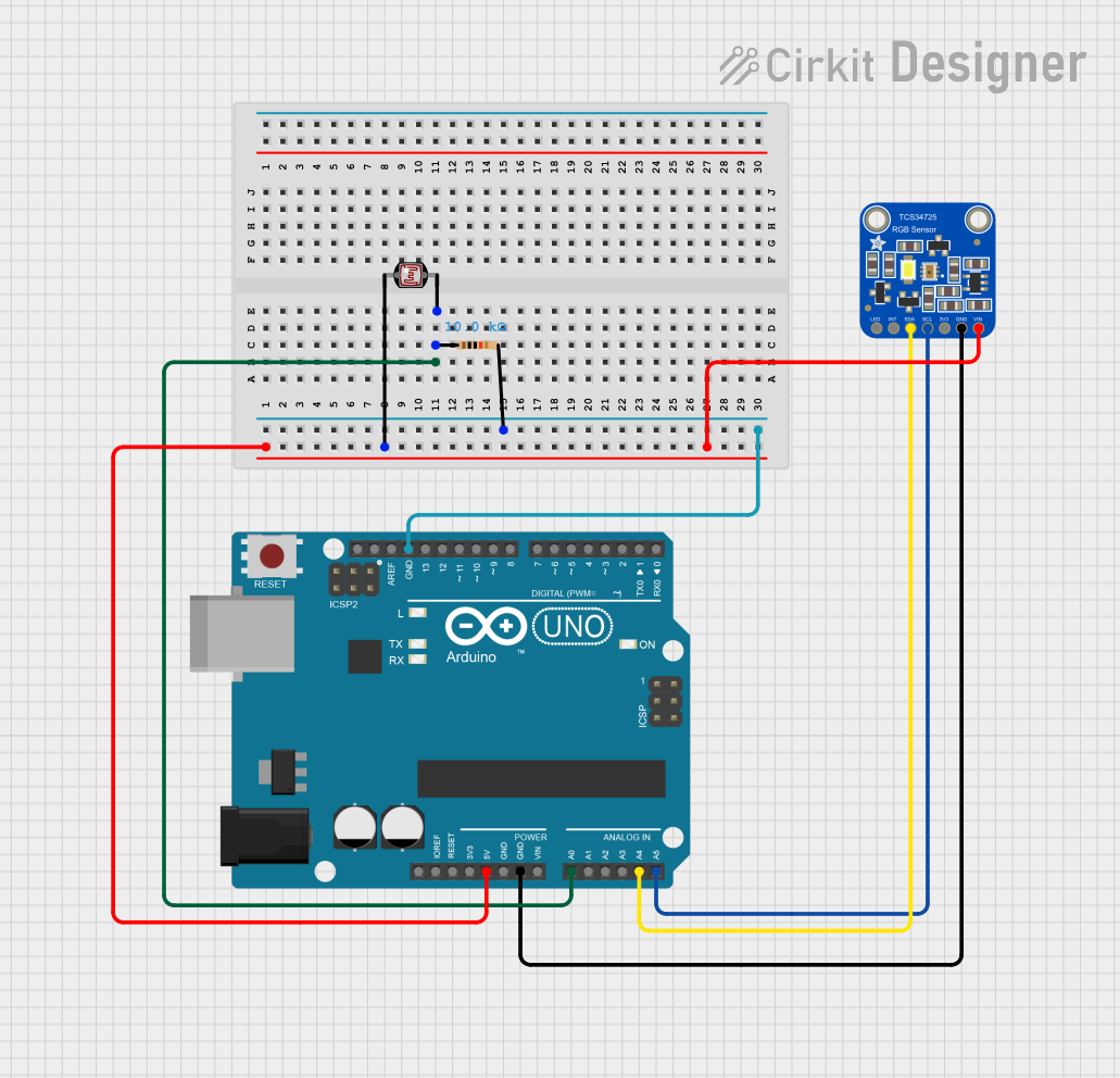
Integration into a Circuit

To use the DFRobot Tristimulus Color Sensor in a circuit:

  1. Connect the VDD pin to a 2.7V to 3.6V power supply.
  2. Connect the GND pin to the ground of the power supply.
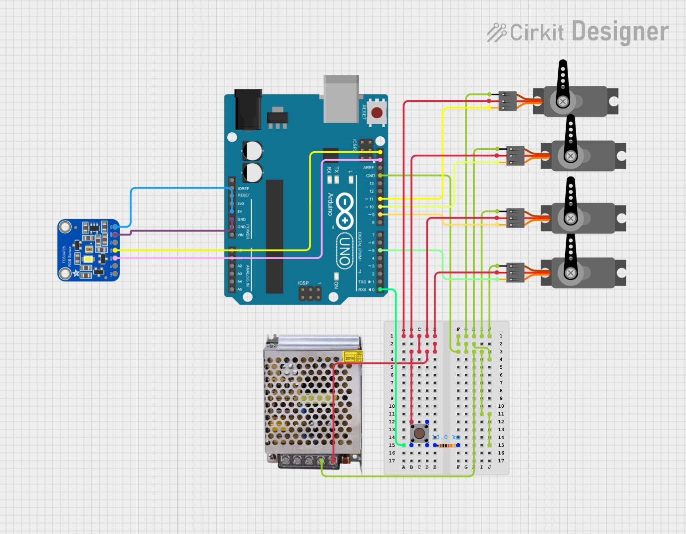
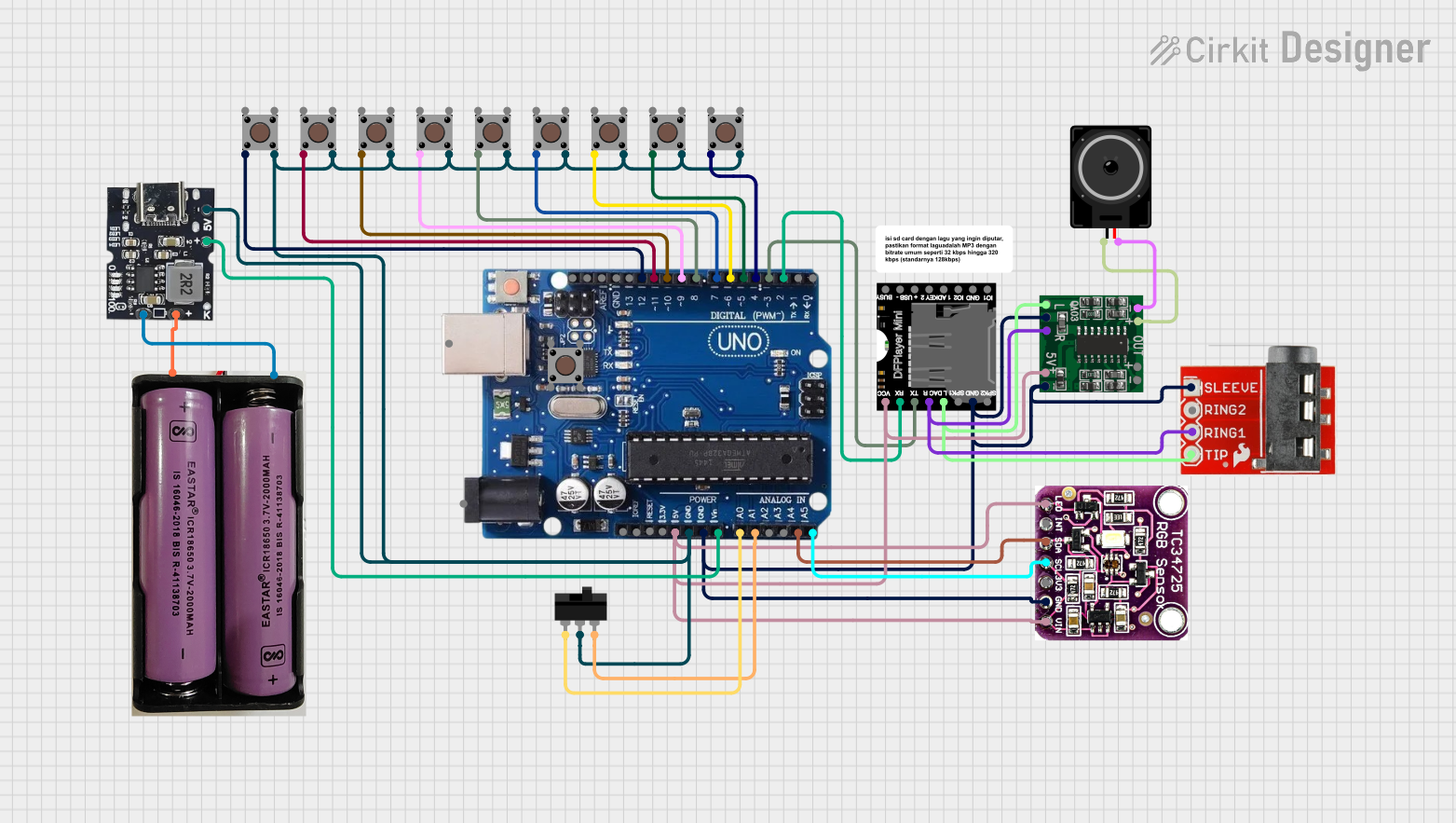
  3. Interface the SCL and SDA pins with the I2C bus of a microcontroller, such as an Arduino UNO.
  4. The INT pin can be connected to an external interrupt pin on the microcontroller if interrupt-driven measurements are required.
  5. The ADDR pin can be used to set the I2C address if multiple devices are connected to the same I2C bus.

Best Practices

  • Ensure that the power supply is stable and within the specified voltage range.
  • Use pull-up resistors on the SCL and SDA lines for reliable I2C communication.
  • Avoid exposing the sensor to direct sunlight or strong artificial light sources that could saturate the sensor.
  • Calibrate the sensor for the specific application environment to achieve accurate color measurements.

Example Code for Arduino UNO

#include <Wire.h>

// TCS3430 I2C address is 0x39(57)
#define Addr 0x39

void setup() {
  // Initialise I2C communication as MASTER
  Wire.begin();
  // Initialise serial communication, set baud rate = 9600
  Serial.begin(9600);
  
  // Start I2C Transmission
  Wire.beginTransmission(Addr);
  // Select enable register
  Wire.write(0x80);
  // Power ON, RGBC enable, wait time disable
  Wire.write(0x03);
  // Stop I2C Transmission
  Wire.endTransmission();
  
  // Start I2C Transmission
  Wire.beginTransmission(Addr);
  // Select ALS time register
  Wire.write(0x81);
  // Atime = 700 ms, Max count = 65535 cycles
  Wire.write(0x00);
  // Stop I2C Transmission
  Wire.endTransmission();
  
  // Start I2C Transmission
  Wire.beginTransmission(Addr);
  // Select Wait Time register
  Wire.write(0x83);
  // Wtime = 2.4 ms
  Wire.write(0xFF);
  // Stop I2C Transmission
  Wire.endTransmission();
  
  delay(800);
}

void loop() {
  unsigned int data[4];
  
  // Start I2C Transmission
  Wire.beginTransmission(Addr);
  // Select data register
  Wire.write(0x94);
  // Stop I2C Transmission
  Wire.endTransmission();
  
  // Request 8 bytes of data
  Wire.requestFrom(Addr, 8);
  
  // Read the 8 bytes of data
  // red lsb, red msb, green lsb, green msb, blue lsb, blue msb
  if (Wire.available() == 8) {
    data[0] = Wire.read();
    data[0] |= Wire.read() << 8;
    data[1] = Wire.read();
    data[1] |= Wire.read() << 8;
    data[2] = Wire.read();
    data[2] |= Wire.read() << 8;
  }
  
  // Convert the data
  float red = data[0] * 1.00;
  float green = data[1] * 1.00;
  float blue = data[2] * 1.00;
  
  // Output data to the serial monitor
  Serial.print("Red Color Luminance : ");
  Serial.print(red);
  Serial.println(" lux");
  Serial.print("Green Color Luminance : ");
  Serial.print(green);
  Serial.println(" lux");
  Serial.print("Blue Color Luminance : ");
  Serial.print(blue);
  Serial.println(" lux");
  
  delay(500);
}

Troubleshooting and FAQs

Common Issues

  • Sensor Not Responding: Ensure that the sensor is correctly powered and that the I2C connections are secure. Check for proper pull-up resistors on the I2C lines.
  • Inaccurate Color Readings: Calibrate the sensor for the lighting conditions of the environment. Avoid placing the sensor in direct light or near reflective surfaces.
  • I2C Communication Errors: Verify the I2C address and ensure there are no conflicts with other devices on the bus.

FAQs

Q: Can the sensor detect color in complete darkness? A: No, the sensor requires some level of ambient light to detect and measure colors accurately.

Q: Is it possible to change the I2C address of the sensor? A: Yes, the I2C address can be changed by connecting the ADDR pin to VDD or GND.

Q: How can I integrate this sensor with a non-Arduino microcontroller? A: The sensor uses standard I2C communication, so it can be interfaced with any microcontroller that supports I2C with the appropriate voltage levels.

Q: What is the maximum distance from an object that the sensor can accurately detect color? A: The maximum sensing distance depends on the object's color and ambient light conditions. It is recommended to place the sensor as close to the object as possible without touching it.

For further assistance, please contact DFRobot's technical support.