
How to Use 7-SEGMENT-4DIGIT: Examples, Pinouts, and Specs
 Design with 7-SEGMENT-4DIGIT in Cirkit Designer
Introduction
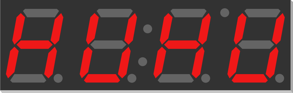
The 7-SEGMENT-4DIGIT display is a versatile electronic component designed to visually represent decimal numbers. It consists of four individual 7-segment digits, each made up of seven LED segments arranged in a figure-eight pattern. By illuminating specific segments, the display can represent numbers from 0 to 9.
This component is widely used in digital clocks, counters, timers, and other devices requiring numeric displays. Its compact design and ease of use make it a popular choice for both hobbyists and professionals.
Explore Projects Built with 7-SEGMENT-4DIGIT
 Open Project in Cirkit Designer
 Open Project in Cirkit Designer
 Open Project in Cirkit Designer
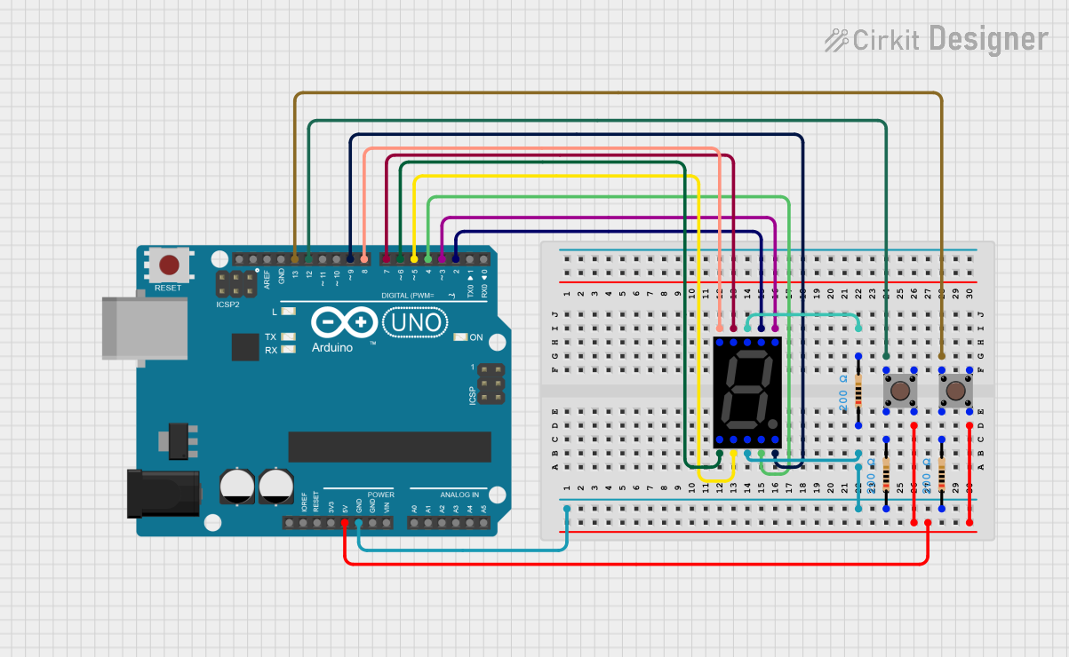 Open Project in Cirkit Designer
Explore Projects Built with 7-SEGMENT-4DIGIT
Open Project in Cirkit DesignerOpen Project in Cirkit DesignerOpen Project in Cirkit DesignerOpen Project in Cirkit DesignerTechnical Specifications
- Type: 4-digit 7-segment display
- Operating Voltage: Typically 3.3V to 5V (check specific model datasheet)
- Current Consumption: ~20mA per segment (varies by model)
- Display Type: Common Cathode or Common Anode (varies by model)
- Segment Color: Red (other colors may be available)
- Digit Height: Typically 0.36 inches to 1 inch (varies by model)
- Number of Pins: 12 to 16 (depending on configuration)
Pin Configuration and Descriptions
Below is a typical pinout for a 7-SEGMENT-4DIGIT display. Note that the exact pin configuration may vary depending on the manufacturer and model, so always refer to the datasheet for your specific component.
| Pin Number | Label | Description |
|---|---|---|
| 1 | Digit 1 (D1) | Controls the first digit (leftmost) |
| 2 | Segment A | Controls the "A" segment of all digits |
| 3 | Segment B | Controls the "B" segment of all digits |
| 4 | Digit 2 (D2) | Controls the second digit |
| 5 | Segment C | Controls the "C" segment of all digits |
| 6 | Digit 3 (D3) | Controls the third digit |
| 7 | Segment D | Controls the "D" segment of all digits |
| 8 | Segment E | Controls the "E" segment of all digits |
| 9 | Digit 4 (D4) | Controls the fourth digit (rightmost) |
| 10 | Segment F | Controls the "F" segment of all digits |
| 11 | Segment G | Controls the "G" segment of all digits |
| 12 | Decimal Point | Controls the decimal point (shared across all digits) |
Note: For common cathode displays, all cathodes are connected together and must be grounded. For common anode displays, all anodes are connected together and must be connected to the supply voltage.
Usage Instructions
How to Use the Component in a Circuit
- Determine the Type: Identify whether your display is common cathode or common anode. This will affect how you connect it to your circuit.
- Connect the Pins:
- For a common cathode display, connect the common cathode pin(s) to ground.
- For a common anode display, connect the common anode pin(s) to the supply voltage.
- Control the Segments: Use a microcontroller (e.g., Arduino UNO) or a driver IC (e.g., MAX7219) to control the individual segments and digits. Each segment requires a current-limiting resistor (typically 220Ω to 1kΩ) to prevent damage.
- Multiplexing: Since all digits share the same segment pins, multiplexing is required to control each digit individually. This involves rapidly switching between digits to create the illusion of a continuous display.
Important Considerations and Best Practices
- Resistors: Always use current-limiting resistors to protect the LEDs from excessive current.
- Power Supply: Ensure your power supply can handle the total current draw of the display.
- Brightness Control: Use pulse-width modulation (PWM) to adjust the brightness of the display.
- Driver ICs: For ease of use, consider using a driver IC like the MAX7219, which simplifies multiplexing and reduces the number of required microcontroller pins.
Example Code for Arduino UNO
Below is an example of how to control a 7-SEGMENT-4DIGIT display using an Arduino UNO. This example assumes a common cathode display.
// Define segment pins (A-G and DP)
const int segmentPins[] = {2, 3, 4, 5, 6, 7, 8, 9};
// Define digit control pins (D1-D4)
const int digitPins[] = {10, 11, 12, 13};

// Segment patterns for digits 0-9
const byte digitPatterns[] = {
  0b00111111, // 0
  0b00000110, // 1
  0b01011011, // 2
  0b01001111, // 3
  0b01100110, // 4
  0b01101101, // 5
  0b01111101, // 6
  0b00000111, // 7
  0b01111111, // 8
  0b01101111  // 9
};

void setup() {
  // Set segment pins as outputs
  for (int i = 0; i < 8; i++) {
    pinMode(segmentPins[i], OUTPUT);
  }
  // Set digit pins as outputs
  for (int i = 0; i < 4; i++) {
    pinMode(digitPins[i], OUTPUT);
  }
}

void loop() {
  // Display the number "1234"
  displayNumber(1234);
}

void displayNumber(int number) {
  for (int digit = 0; digit < 4; digit++) {
    // Extract the current digit
    int currentDigit = (number / (int)pow(10, 3 - digit)) % 10;

    // Set the segment pins
    for (int i = 0; i < 8; i++) {
      digitalWrite(segmentPins[i], bitRead(digitPatterns[currentDigit], i));
    }

    // Enable the current digit
    digitalWrite(digitPins[digit], LOW);
    delay(5); // Small delay for multiplexing
    digitalWrite(digitPins[digit], HIGH);
  }
}
Note: Adjust the pin numbers and delay as needed for your specific setup.
Troubleshooting and FAQs
Common Issues
Segments Not Lighting Up:
- Check the wiring and ensure all connections are secure.
- Verify that the current-limiting resistors are correctly installed.
- Ensure the power supply voltage matches the display's requirements.
Incorrect Digits Displayed:
- Double-check the segment-to-pin mapping in your code.
- Ensure the correct type (common cathode or common anode) is selected in your circuit.
Flickering Display:
- Increase the multiplexing frequency in your code.
- Ensure the power supply can handle the current draw.
Dim Display:
- Verify the resistor values; they may be too high.
- Check the power supply voltage and current capacity.
FAQs
Q: Can I control this display without a microcontroller?
A: Yes, you can use a driver IC like the MAX7219 or manually control the segments using switches, but this is less practical for dynamic displays.
Q: How do I know if my display is common cathode or common anode?
A: Refer to the datasheet or test the display by connecting a single segment to power and ground. For common cathode, the cathode pin connects to ground; for common anode, the anode pin connects to power.
Q: Can I use this display with a 3.3V microcontroller?
A: Yes, but ensure the forward voltage of the LEDs is compatible, and adjust resistor values accordingly.