How to Use lora ra 02: Examples, Pinouts, and Specs
Introduction
The LoRa RA-02 is a low-power, long-range transceiver module designed for wireless communication using LoRa (Long Range) modulation technology. Manufactured by LoRa, this module enables reliable data transmission over distances of several kilometers, making it ideal for Internet of Things (IoT) applications. Its robust design and low power consumption make it suitable for remote sensing, smart agriculture, industrial automation, and other wireless communication systems.
Explore Projects Built with lora ra 02
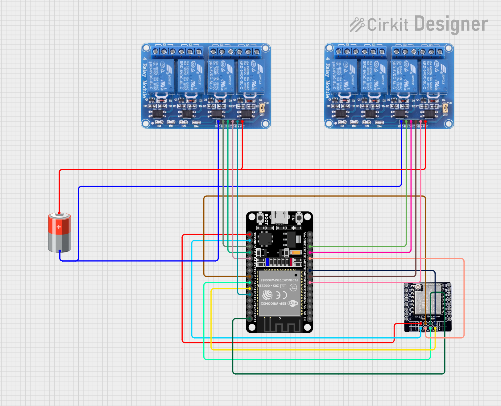
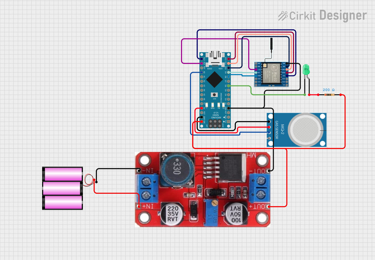

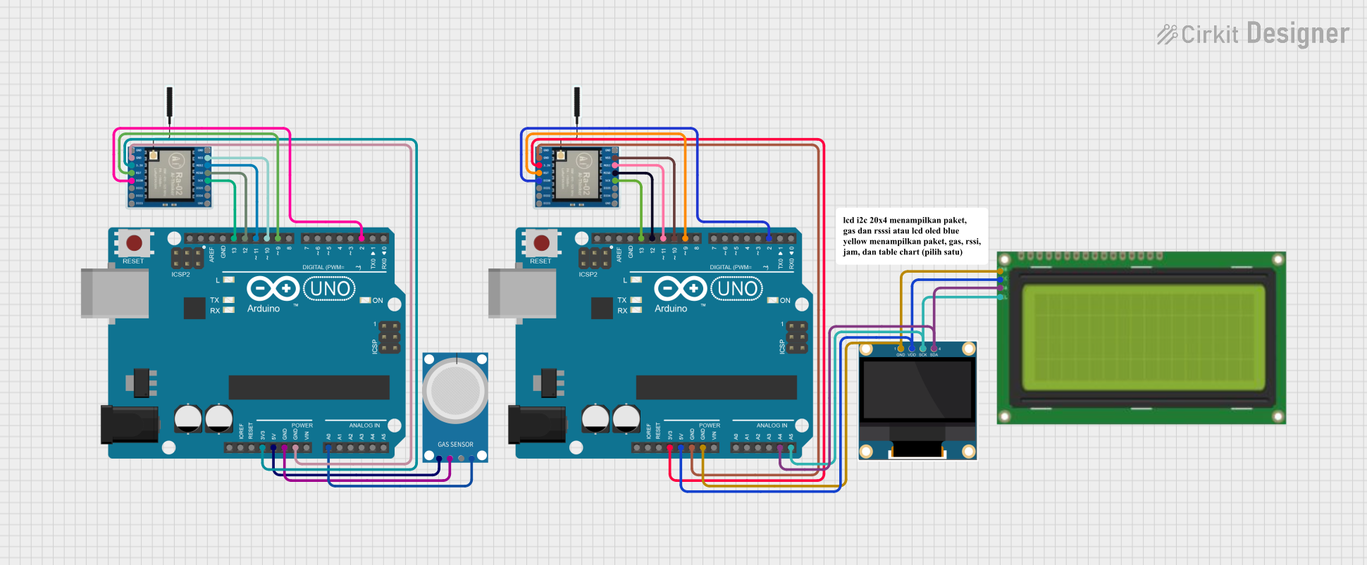
Explore Projects Built with lora ra 02
Common Applications
- IoT networks for remote monitoring and control
- Smart agriculture (e.g., soil moisture sensors, weather stations)
- Industrial automation and telemetry
- Smart cities (e.g., parking sensors, street lighting control)
- Environmental monitoring systems
- Asset tracking and geolocation
Technical Specifications
The LoRa RA-02 module is built to deliver high performance in long-range communication while maintaining low power consumption. Below are its key technical specifications:
| Parameter | Value |
|---|---|
| Manufacturer | LoRa |
| Part ID | RA-02 |
| Frequency Range | 410 MHz to 525 MHz |
| Modulation Technology | LoRa (Long Range) |
| Communication Range | Up to 10 km (line of sight) |
| Data Rate | 0.3 kbps to 37.5 kbps |
| Supply Voltage | 1.8V to 3.7V |
| Operating Current | 10.8 mA (transmit mode) |
| Sleep Current | < 1 µA |
| Output Power | Up to 20 dBm |
| Sensitivity | -148 dBm |
| Operating Temperature | -40°C to +85°C |
| Dimensions | 16 mm x 16 mm x 2 mm |
Pin Configuration and Descriptions
The LoRa RA-02 module has 16 pins, each serving a specific function. Below is the pinout and description:
| Pin Number | Pin Name | Description |
|---|---|---|
| 1 | GND | Ground connection |
| 2 | DIO0 | Digital I/O pin 0 (interrupt output) |
| 3 | DIO1 | Digital I/O pin 1 |
| 4 | DIO2 | Digital I/O pin 2 |
| 5 | DIO3 | Digital I/O pin 3 |
| 6 | DIO4 | Digital I/O pin 4 |
| 7 | DIO5 | Digital I/O pin 5 |
| 8 | GND | Ground connection |
| 9 | MISO | SPI Master In Slave Out |
| 10 | MOSI | SPI Master Out Slave In |
| 11 | SCK | SPI Clock |
| 12 | NSS | SPI Chip Select |
| 13 | RESET | Reset pin (active low) |
| 14 | 3.3V | Power supply (3.3V) |
| 15 | ANT | Antenna connection |
| 16 | GND | Ground connection |
Usage Instructions
How to Use the LoRa RA-02 in a Circuit
- Power Supply: Connect the 3.3V pin to a regulated 3.3V power source. Ensure the power supply can provide sufficient current for the module's operation.
- SPI Communication: Connect the SPI pins (MISO, MOSI, SCK, NSS) to the corresponding SPI pins on your microcontroller.
- Antenna: Attach a suitable 433 MHz or 470 MHz antenna to the ANT pin for optimal performance.
- Reset: Use the RESET pin to initialize the module. Pull it low momentarily to reset the module.
- Digital I/O Pins: Use the DIO pins for interrupts or additional control signals as required by your application.
Important Considerations
- Voltage Levels: The RA-02 operates at 3.3V logic levels. If using a 5V microcontroller (e.g., Arduino UNO), use a level shifter to avoid damaging the module.
- Antenna Placement: Ensure the antenna is placed away from metal objects or other sources of interference to maximize range.
- Power Supply Decoupling: Add a 10 µF capacitor near the power pins to stabilize the power supply and reduce noise.
- Heat Dissipation: Avoid prolonged operation at maximum output power to prevent overheating.
Example: Connecting LoRa RA-02 to Arduino UNO
Below is an example of how to connect the LoRa RA-02 to an Arduino UNO and send data using the LoRa library.
Wiring Diagram
| RA-02 Pin | Arduino UNO Pin |
|---|---|
| 3.3V | 3.3V |
| GND | GND |
| MISO | Pin 12 |
| MOSI | Pin 11 |
| SCK | Pin 13 |
| NSS | Pin 10 |
| RESET | Pin 9 |
| DIO0 | Pin 2 |
Arduino Code
#include <SPI.h>
#include <LoRa.h>

// Define LoRa module pins
#define SS 10       // NSS pin
#define RST 9       // Reset pin
#define DIO0 2      // DIO0 pin

void setup() {
  // Initialize serial communication for debugging
  Serial.begin(9600);
  while (!Serial);

  // Initialize LoRa module
  Serial.println("Initializing LoRa...");
  LoRa.setPins(SS, RST, DIO0); // Set LoRa module pins

  if (!LoRa.begin(433E6)) {    // Initialize LoRa at 433 MHz
    Serial.println("LoRa initialization failed!");
    while (1);
  }

  Serial.println("LoRa initialized successfully!");
}

void loop() {
  // Send a test message
  Serial.println("Sending message...");
  LoRa.beginPacket();
  LoRa.print("Hello, LoRa!");
  LoRa.endPacket();

  delay(5000); // Wait 5 seconds before sending the next message
}
Troubleshooting and FAQs
Common Issues
Module Not Responding
- Cause: Incorrect wiring or power supply issues.
- Solution: Double-check all connections and ensure the module is powered with a stable 3.3V supply.
Short Communication Range
- Cause: Poor antenna placement or interference.
- Solution: Use a high-quality antenna and place it away from obstructions or interference sources.
LoRa Initialization Fails
- Cause: Incorrect SPI connections or mismatched frequency settings.
- Solution: Verify SPI connections and ensure the frequency matches the module's operating range.
Overheating
- Cause: Prolonged operation at maximum output power.
- Solution: Reduce the output power or add a heat sink to the module.
FAQs
Can I use the RA-02 with a 5V microcontroller?
- Yes, but you must use a level shifter to convert 5V logic to 3.3V.
What is the maximum range of the RA-02?
- The module can achieve up to 10 km in line-of-sight conditions with a proper antenna.
Does the RA-02 support bidirectional communication?
- Yes, the RA-02 supports both transmitting and receiving data.
What type of antenna should I use?
- Use a 433 MHz or 470 MHz antenna, depending on your operating frequency.
By following this documentation, you can effectively integrate the LoRa RA-02 module into your projects and troubleshoot common issues.