How to Use Contactor: Examples, Pinouts, and Specs
Introduction
A contactor is an electrically controlled switch designed for switching electrical power circuits. Unlike relays, contactors are specifically engineered to handle higher currents, making them ideal for industrial applications. They are commonly used to control motors, lighting, heating, and other heavy electrical loads. Contactors are essential components in automation systems, ensuring safe and efficient operation of high-power devices.
Explore Projects Built with Contactor


Explore Projects Built with Contactor
Common Applications:
- Motor control in industrial machinery
- HVAC systems for switching compressors and fans
- Lighting control in commercial and industrial settings
- Power distribution systems
- Electric heating systems
Technical Specifications
Key Technical Details:
- Voltage Rating: Typically ranges from 24V to 1000V (AC or DC, depending on the model)
- Current Rating: Can handle currents from 10A to over 1000A
- Coil Voltage: Commonly available in 12V, 24V, 48V, 110V, 220V, or 380V
- Contact Configuration: Single-pole, double-pole, or three-pole (SPST, DPST, 3PST, etc.)
- Mechanical Life: Typically over 1 million operations
- Electrical Life: Typically over 100,000 operations under rated load
- Operating Temperature Range: -25°C to +55°C (varies by model)
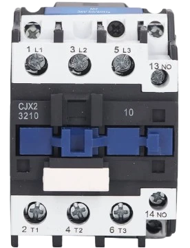
Pin Configuration and Descriptions:
The pin configuration of a contactor depends on its design. Below is a general example for a 3-pole contactor with a control coil:
| Pin Name | Description |
|---|---|
| L1, L2, L3 | Input terminals for the three-phase power supply |
| T1, T2, T3 | Output terminals connected to the load (e.g., motor, heater) |
| A1, A2 | Coil terminals for controlling the contactor (connected to the control voltage) |
| NO (Normally Open) | Auxiliary contact for additional control or feedback circuits |
| NC (Normally Closed) | Auxiliary contact for additional control or feedback circuits |
Note: The exact pin configuration may vary depending on the manufacturer and model. Always refer to the datasheet for specific details.
Usage Instructions
How to Use a Contactor in a Circuit:
- Determine the Ratings: Ensure the contactor's voltage and current ratings match the requirements of your load and power supply.
- Connect the Power Supply:
- Connect the input power lines to the L1, L2, and L3 terminals.
- Connect the load (e.g., motor) to the T1, T2, and T3 terminals.
- Control the Coil:
- Apply the appropriate control voltage to the A1 and A2 terminals to energize the coil.
- When the coil is energized, the main contacts close, allowing current to flow to the load.
- Use Auxiliary Contacts (if available):
- Auxiliary contacts (NO/NC) can be used for additional control logic or feedback to a controller.
- Safety Precautions:
- Always use proper fuses or circuit breakers to protect the circuit.
- Ensure the contactor is installed in a well-ventilated enclosure to prevent overheating.
Important Considerations:
- Avoid Overloading: Ensure the contactor's current rating exceeds the maximum load current.
- Coil Voltage Compatibility: Verify that the control voltage matches the coil voltage rating.
- Arc Suppression: For DC loads, consider using arc suppression circuits to protect the contacts.
- Noise Reduction: Use snubber circuits or RC filters to reduce electrical noise caused by switching.
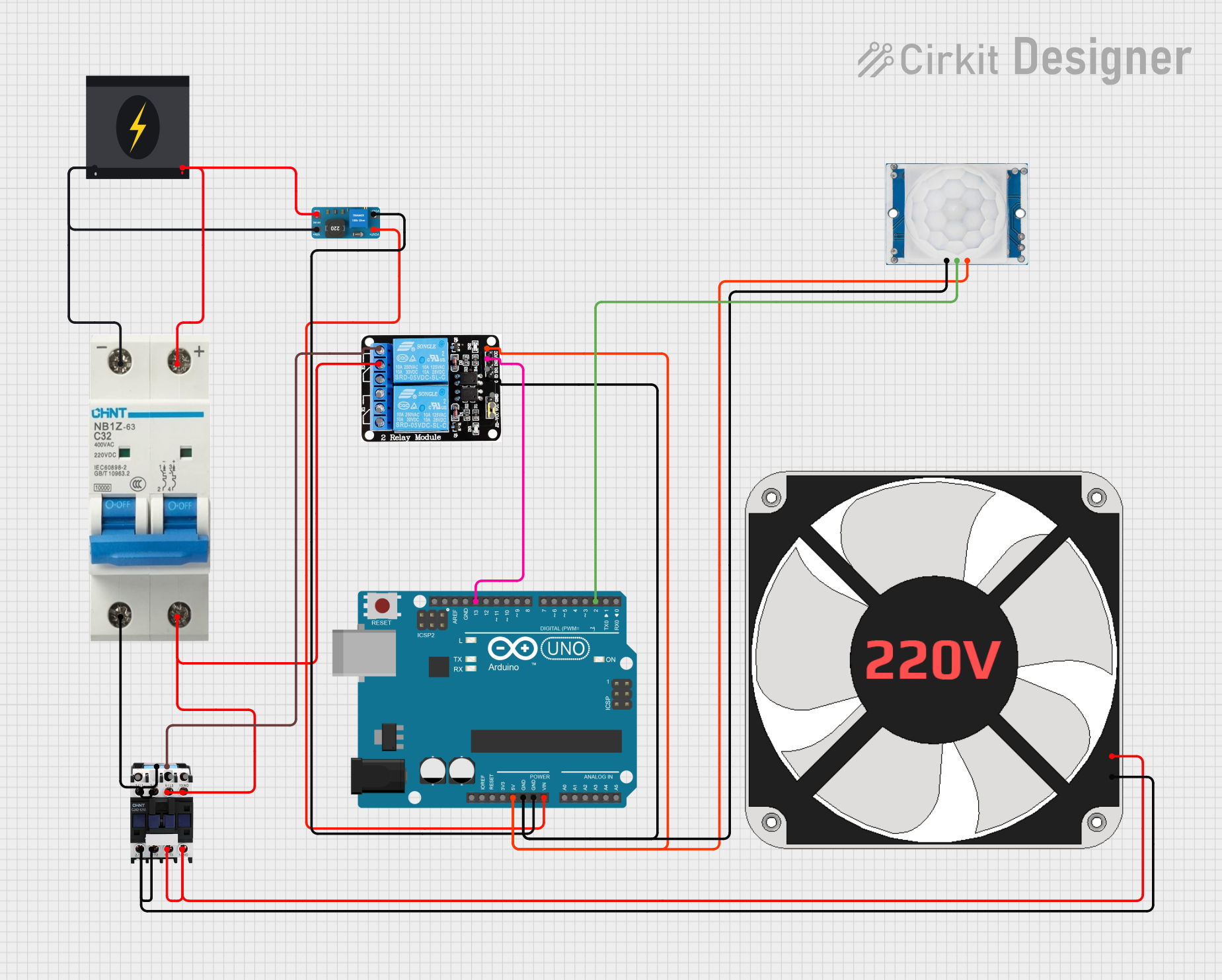
Example: Controlling a Contactor with an Arduino UNO
Below is an example of how to control a 12V DC contactor using an Arduino UNO and a relay module:
// Example: Controlling a 12V DC contactor with Arduino UNO
// This code energizes the contactor for 5 seconds, then de-energizes it.

const int relayPin = 7; // Pin connected to the relay module

void setup() {
  pinMode(relayPin, OUTPUT); // Set relay pin as output
  digitalWrite(relayPin, LOW); // Ensure relay is off initially
}

void loop() {
  digitalWrite(relayPin, HIGH); // Turn on the relay (energize contactor)
  delay(5000); // Keep the contactor energized for 5 seconds
  digitalWrite(relayPin, LOW); // Turn off the relay (de-energize contactor)
  delay(5000); // Wait for 5 seconds before repeating
}
Note: Use a relay module to interface the Arduino with the contactor, as the Arduino cannot directly drive the contactor's coil.
Troubleshooting and FAQs
Common Issues and Solutions:
Contactor Does Not Energize:
- Cause: Incorrect coil voltage or insufficient power supply.
- Solution: Verify the control voltage matches the coil rating and check the power supply.
Contacts Overheat or Weld Together:
- Cause: Overloading or switching high inrush currents.
- Solution: Ensure the contactor's current rating exceeds the load requirements. Use a soft starter or inrush current limiter if necessary.
Excessive Noise During Operation:
- Cause: Electrical noise or vibration in the coil.
- Solution: Use a snubber circuit or RC filter across the coil terminals.
Frequent Contact Wear:
- Cause: High switching frequency or arcing.
- Solution: Reduce the switching frequency or use arc suppression techniques.
Contactor Fails to Release:
- Cause: Residual magnetism or mechanical issues.
- Solution: Check for mechanical obstructions and ensure proper coil de-energization.
FAQs:
Q: Can I use a contactor for DC loads?
A: Yes, but ensure the contactor is rated for DC operation. DC contactors often require larger gaps between contacts to handle arcing.Q: What is the difference between a relay and a contactor?
A: Relays are designed for low-power applications, while contactors are built to handle high-power loads and are more robust.Q: How do I select the right contactor for my application?
A: Consider the voltage, current, and type of load (AC or DC). Also, check the coil voltage and any additional features like auxiliary contacts.Q: Can I manually operate a contactor?
A: Some contactors have a manual override feature, but this is typically for testing or maintenance purposes only.
By following this documentation, you can effectively use and troubleshoot contactors in various applications. Always consult the manufacturer's datasheet for specific details about your contactor model.