Cirkit Designer
Your all-in-one circuit design IDE
Home /
Component Documentation
How to Use V_REG MIC5219: Examples, Pinouts, and Specs
Introduction
The V_REG MIC5219 is a high-performance, low dropout regulator (LDO) designed to provide a stable and reliable power supply in a variety of electronic applications. This LDO is capable of delivering up to 150 mA of output current with a low dropout voltage, making it an excellent choice for battery-powered devices, portable electronics, and microcontroller-based systems, including those using Arduino UNO.
Explore Projects Built with V_REG MIC5219
Sound-Activated LED Lighting with ESP32 and INMP441 Microphone
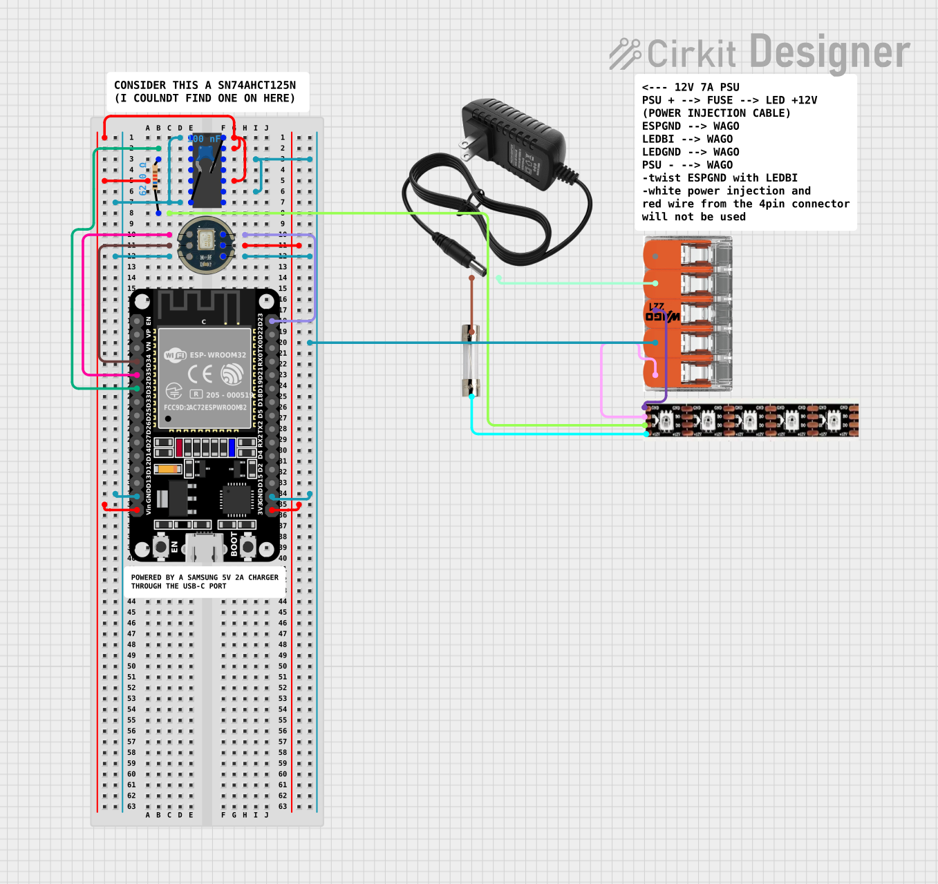
This circuit features an ESP32 microcontroller interfacing with an INMP441 microphone module and controlling a WS2815 LED strip, with signal conditioning provided by an SN74AHC14 hex inverter. It includes a 12V power supply with a 5A fuse for protection and uses a ceramic capacitor for voltage regulation.
ESP32 and RFID-RC522 Based Battery-Powered Access Control System with I2C LCD Display
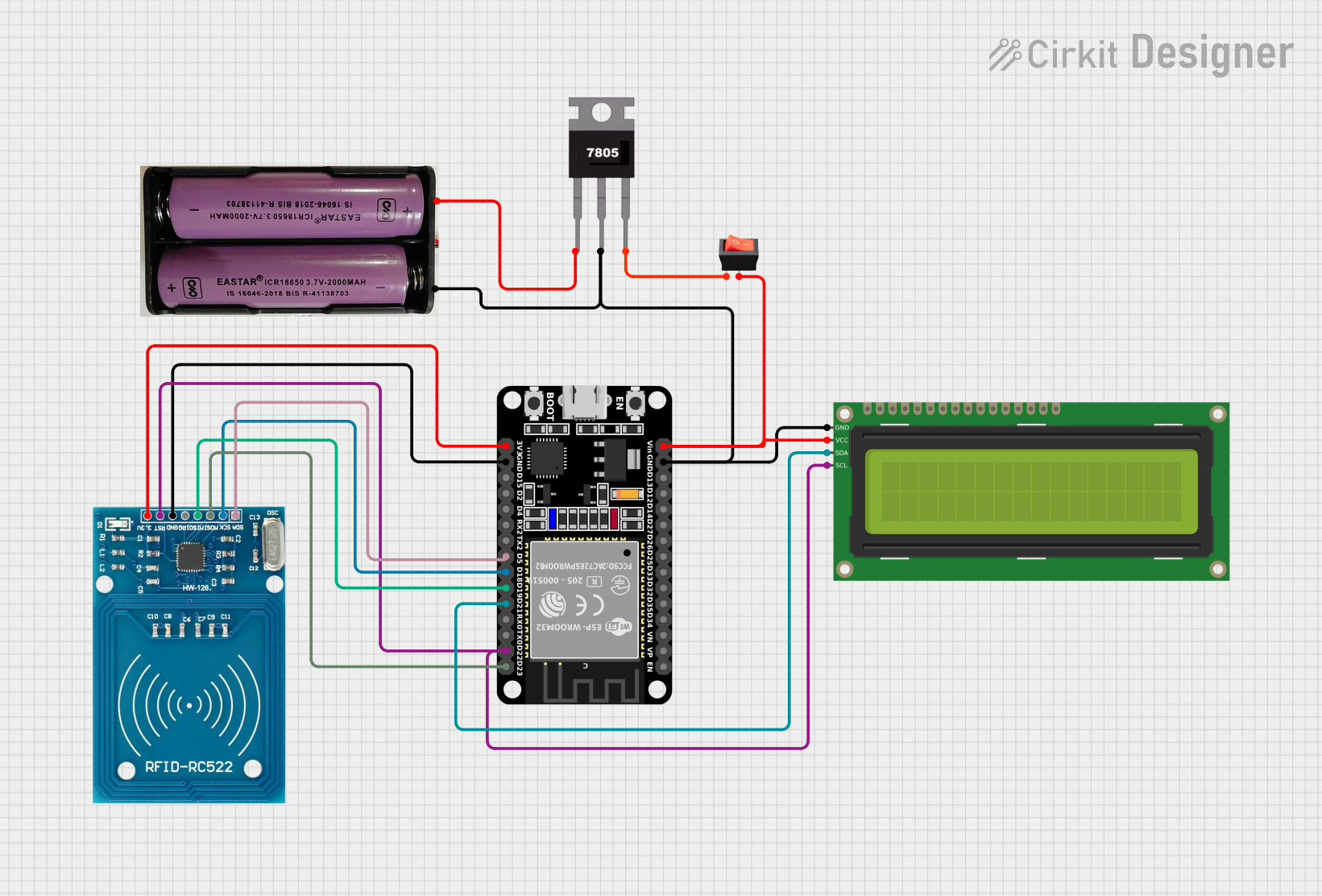
This circuit is a microcontroller-based system using an ESP32 to interface with an RFID reader (RFID-RC522) and a 16x2 I2C LCD display. The system is powered by a 7.4V battery regulated to 5V using a 7805 voltage regulator, and it includes a rocker switch for power control.
Raspberry Pi 5 RFID Access Control System with LCD Feedback and Dual Motor Control
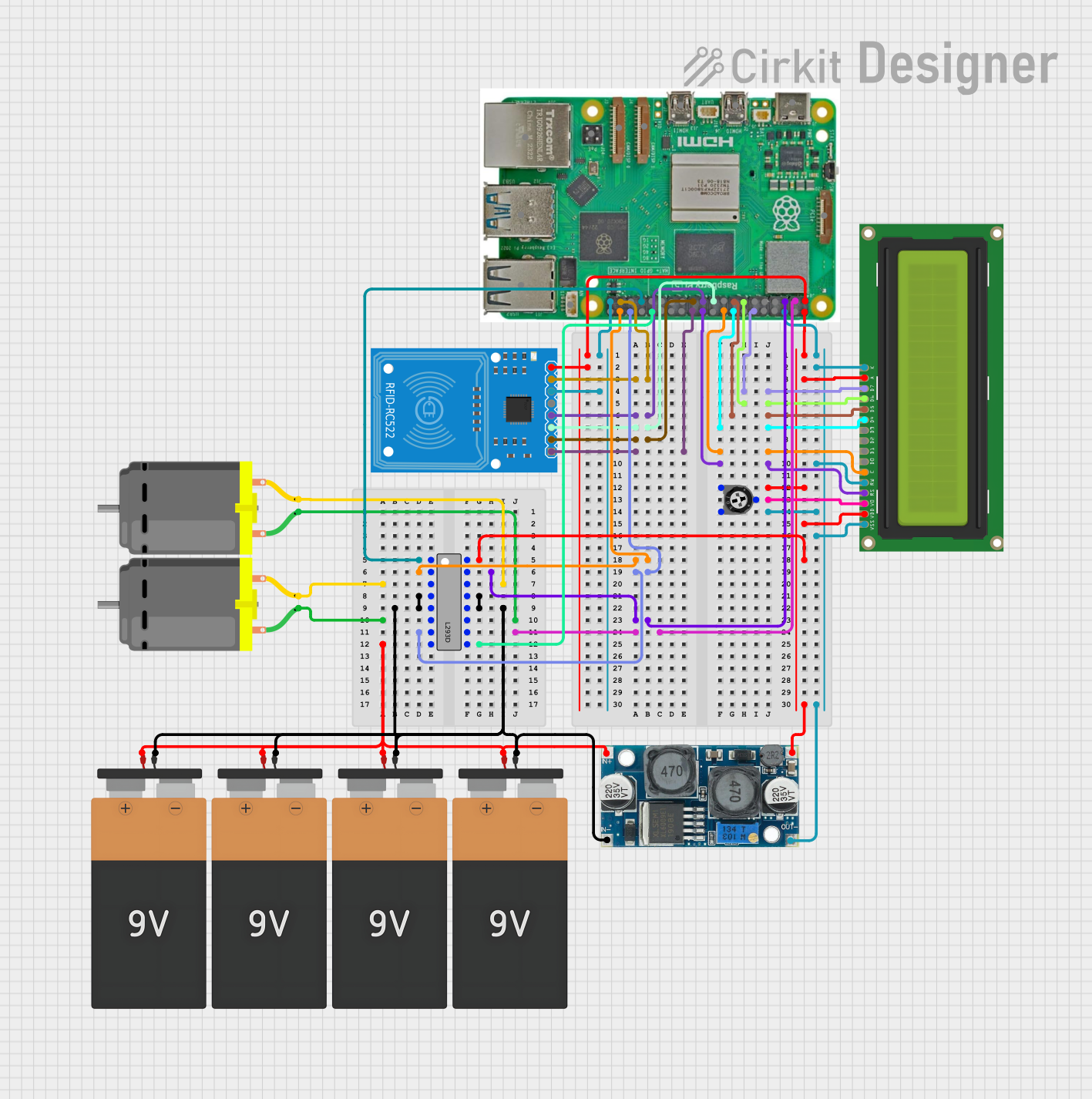
This circuit features a Raspberry Pi 5 as the central controller, interfaced with an RFID-RC522 module for RFID reading capabilities and a 16x2 LCD display for output visualization. The Raspberry Pi controls two DC motors via an L293D motor driver, with speed or direction potentially adjusted by a trimmer potentiometer. Power regulation is managed by an XL6009 voltage regulator, and multiple 9V batteries are used to supply power to the system.
Raspberry Pi Zero-Based Audio Visualizer with OLED Display and INMP441 Microphone
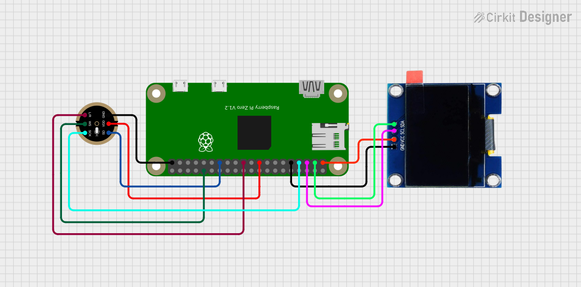
This circuit features a Raspberry Pi Zero connected to an INMP441 MEMS microphone and a 1.3" OLED display. The Raspberry Pi Zero communicates with the OLED display via I2C (using GPIO2 for SDA and GPIO3 for SCL), and it interfaces with the INMP441 microphone using I2S (with GPIO4 for SCK, GPIO9 for L/R selection, ID_SD for SD, and GPIO12 for WS). The circuit is designed for audio input through the microphone and visual output on the OLED display, likely for applications such as sound visualization or audio monitoring.
Explore Projects Built with V_REG MIC5219
Sound-Activated LED Lighting with ESP32 and INMP441 Microphone
This circuit features an ESP32 microcontroller interfacing with an INMP441 microphone module and controlling a WS2815 LED strip, with signal conditioning provided by an SN74AHC14 hex inverter. It includes a 12V power supply with a 5A fuse for protection and uses a ceramic capacitor for voltage regulation.
ESP32 and RFID-RC522 Based Battery-Powered Access Control System with I2C LCD Display
This circuit is a microcontroller-based system using an ESP32 to interface with an RFID reader (RFID-RC522) and a 16x2 I2C LCD display. The system is powered by a 7.4V battery regulated to 5V using a 7805 voltage regulator, and it includes a rocker switch for power control.
Raspberry Pi 5 RFID Access Control System with LCD Feedback and Dual Motor Control
This circuit features a Raspberry Pi 5 as the central controller, interfaced with an RFID-RC522 module for RFID reading capabilities and a 16x2 LCD display for output visualization. The Raspberry Pi controls two DC motors via an L293D motor driver, with speed or direction potentially adjusted by a trimmer potentiometer. Power regulation is managed by an XL6009 voltage regulator, and multiple 9V batteries are used to supply power to the system.
Raspberry Pi Zero-Based Audio Visualizer with OLED Display and INMP441 Microphone
This circuit features a Raspberry Pi Zero connected to an INMP441 MEMS microphone and a 1.3" OLED display. The Raspberry Pi Zero communicates with the OLED display via I2C (using GPIO2 for SDA and GPIO3 for SCL), and it interfaces with the INMP441 microphone using I2S (with GPIO4 for SCK, GPIO9 for L/R selection, ID_SD for SD, and GPIO12 for WS). The circuit is designed for audio input through the microphone and visual output on the OLED display, likely for applications such as sound visualization or audio monitoring.
Common Applications and Use Cases
- Power supply for microcontrollers and digital logic
- Battery-powered devices
- Portable electronics
- Sensor power supply
- Post-regulation for switching power supplies
Technical Specifications
Key Technical Details
- Output Current: 150 mA
- Dropout Voltage: Typically 380 mV at full load
- Output Voltage Accuracy: ±2%
- Programmable Soft-Start
- Current Limit
- Thermal Shutdown Protection
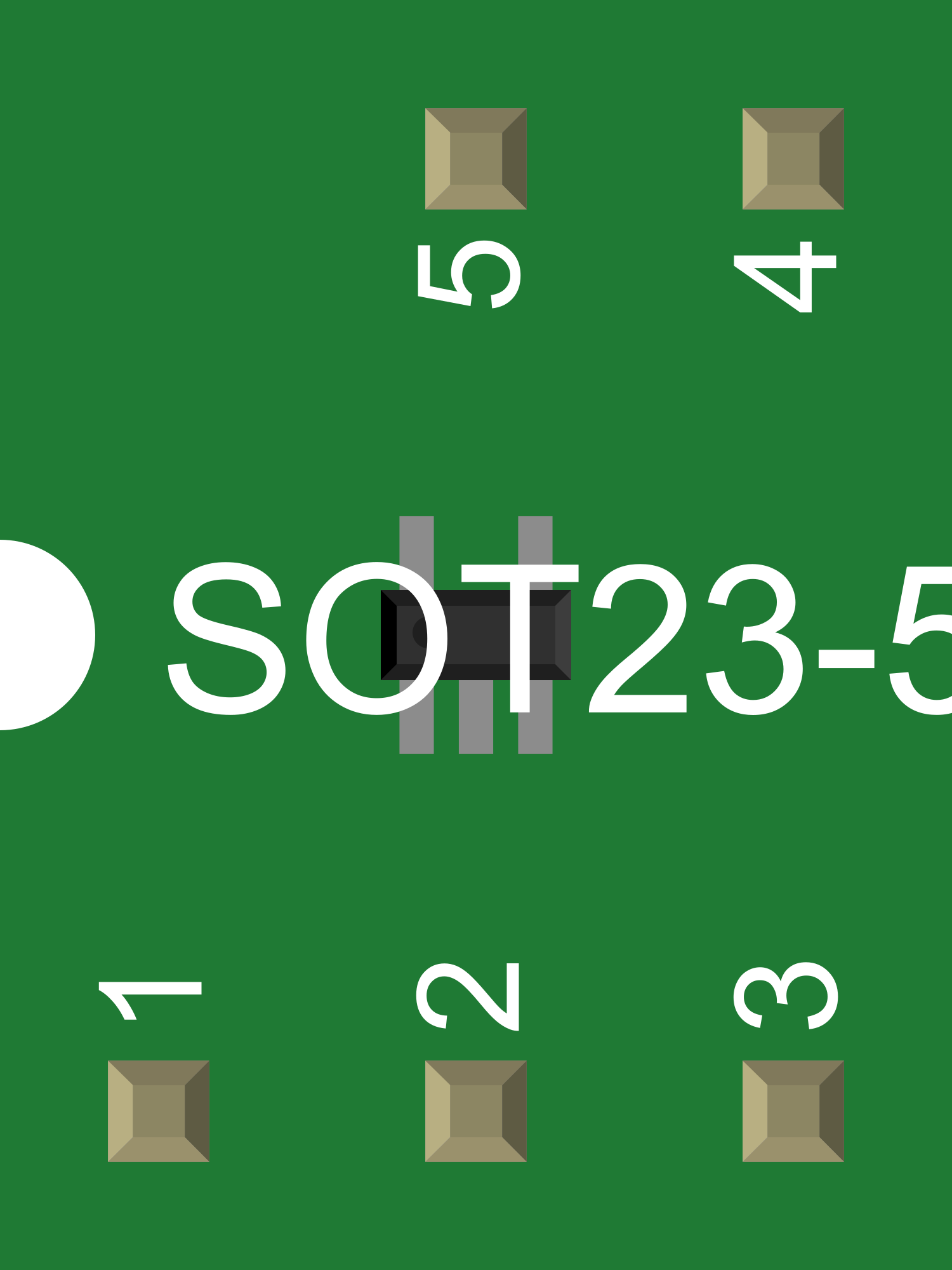
Pin Configuration and Descriptions
| Pin Number | Name | Description |
|---|---|---|
| 1 | IN | Input voltage supply. Connect to the source voltage. |
| 2 | GND | Ground reference for the regulator. |
| 3 | OUT | Regulated output voltage. Connect to the load. |
| 4 | ADJ | Adjustable output voltage setting (for adjustable version). Connect to a resistor divider network to set the output voltage. |
| 5 | EN | Enable pin. Drive high to enable the regulator, low to disable. |
| 6 | SS | Soft-Start control input. Connect a capacitor to determine the soft-start timing. |
| 7 | BYP | Bypass pin. Connect a capacitor to reduce output noise. |
| 8 | CL | Current limit setting. Connect a resistor to set the current limit threshold. |
Usage Instructions
How to Use the Component in a Circuit
- Connect the input voltage to the IN pin, ensuring it is within the specified range for the device.
- Connect the GND pin to the system ground.
- For the fixed voltage version, connect the OUT pin directly to the load. For the adjustable version, use a resistor divider network connected to the ADJ pin to set the desired output voltage.
- Optionally, connect a capacitor to the SS pin to program the soft-start feature.
- Connect a capacitor to the BYP pin to reduce output noise.
- Optionally, connect a resistor to the CL pin to set the current limit threshold.
- Use the EN pin to enable or disable the regulator as needed.
Important Considerations and Best Practices
- Always use capacitors with low equivalent series resistance (ESR) for stability.
- Place input and output capacitors as close to the regulator pins as possible.
- Ensure the input voltage is always higher than the desired output voltage by at least the dropout voltage.
- Do not exceed the maximum input voltage or current ratings.
- Use proper heat sinking if operating near the maximum output current to prevent thermal shutdown.
Troubleshooting and FAQs
Common Issues Users Might Face
- Output Voltage Fluctuation: Ensure capacitors are of good quality and placed close to the regulator pins.
- Thermal Shutdown: Check if the regulator is overheating due to high output current or insufficient heat sinking.
- Regulator Not Enabling: Verify that the EN pin is being driven high properly.
Solutions and Tips for Troubleshooting
- If the output voltage is unstable, check the capacitor ESR values and replace with appropriate ones if necessary.
- For thermal issues, improve heat dissipation by adding a heat sink or reducing the load current.
- Ensure the EN pin voltage is within the specified range for logic high.
Relevant Code for Arduino UNO Connection
// Example code to control the V_REG MIC5219 with an Arduino UNO

const int enablePin = 7; // Connect to the EN pin of the V_REG MIC5219

void setup() {
  pinMode(enablePin, OUTPUT);
  // Start with the regulator disabled
  digitalWrite(enablePin, LOW);
}

void loop() {
  // Enable the regulator
  digitalWrite(enablePin, HIGH);
  delay(1000); // Wait for 1 second

  // Disable the regulator
  digitalWrite(enablePin, LOW);
  delay(1000); // Wait for 1 second
}
Note: This code assumes that the V_REG MIC5219 is connected to an Arduino UNO with the EN pin connected to digital pin 7 on the Arduino. The code simply toggles the regulator on and off every second.
Remember to consult the V_REG MIC5219 datasheet for more detailed information and to ensure proper usage and handling of the device.