Cirkit Designer Logo
Cirkit Designer
Your all-in-one circuit design IDE
Home / 
Component Documentation

How to Use ESP32S3: Examples, Pinouts, and Specs

Image of ESP32S3
Cirkit Designer LogoDesign with ESP32S3 in Cirkit Designer

Introduction

The ESP32S3, manufactured by ESP, is a powerful and versatile system on a chip (SoC) designed for Internet of Things (IoT) applications. It combines integrated Wi-Fi and Bluetooth Low Energy (BLE) capabilities with a dual-core processor, making it suitable for a wide range of smart devices and wireless connectivity solutions. The ESP32S3 is particularly well-suited for applications requiring high performance, low power consumption, and robust wireless communication.

Explore Projects Built with ESP32S3

Use Cirkit Designer to design, explore, and prototype these projects online. Some projects support real-time simulation. Click "Open Project" to start designing instantly!
ESP32-S3 Based Automated Watering System with Ultrasonic Sensing and Data Logging
Image of galon otomatis telegram: A project utilizing ESP32S3 in a practical application
This circuit features an ESP32-S3 microcontroller connected to various peripherals including an HC-SR04 ultrasonic sensor, a water flow sensor, an OLED display, a DS3231 real-time clock (RTC), an SD card module, a water pump, a two-channel relay, and a valve solenoid. The ESP32-S3 manages sensor readings, data logging, and controls the water pump and valve via the relay based on sensor inputs. The circuit is designed for monitoring and controlling water flow, likely in an automated irrigation or fluid management system.
Cirkit Designer LogoOpen Project in Cirkit Designer
ESP32-S3 GPS and Wind Speed Logger with Dual OLED Displays and CAN Bus
Image of esp32-s3-ellipse: A project utilizing ESP32S3 in a practical application
This circuit features an ESP32-S3 microcontroller interfaced with an SD card module, two OLED displays, a GPS module, and a CAN bus module. The ESP32-S3 records GPS data to the SD card, displays speed on one OLED, and shows wind speed from the CAN bus on the other OLED, providing a comprehensive data logging and display system.
Cirkit Designer LogoOpen Project in Cirkit Designer
ESP32-S3 Based Environmental Monitoring and Control System with Data Logging
Image of ESP32: A project utilizing ESP32S3 in a practical application
This circuit features an ESP32-S3 microcontroller interfaced with various sensors and modules, including a DHT22 temperature and humidity sensor, an HC-SR04 ultrasonic sensor, an SGP41 VOC and NOx sensor, and an Adafruit INA260 current and power sensor. The ESP32-S3 also controls a DC motor via a relay and communicates with an SD card and an OLED display. An Arduino UNO is used to read inputs from a rotary encoder, and a step-down buck converter is used to regulate voltage from a 12V battery to power the components.
Cirkit Designer LogoOpen Project in Cirkit Designer
ESP32-S3 Based Vibration Detection System with TFT Display and Power Backup
Image of IOT Thesis: A project utilizing ESP32S3 in a practical application
This circuit features an ESP32-S3 microcontroller connected to various peripherals including an ADXL355 accelerometer, an SW-420 vibration sensor, a buzzer module, and an ILI9341 TFT display. The ESP32-S3 manages sensor inputs and provides output to the display and buzzer. Power management is handled by a 12V to 5V step-down converter, and a UPS ensures uninterrupted power supply, with a rocker switch to control the power flow.
Cirkit Designer LogoOpen Project in Cirkit Designer

Explore Projects Built with ESP32S3

Use Cirkit Designer to design, explore, and prototype these projects online. Some projects support real-time simulation. Click "Open Project" to start designing instantly!
Image of galon otomatis telegram: A project utilizing ESP32S3 in a practical application
ESP32-S3 Based Automated Watering System with Ultrasonic Sensing and Data Logging
This circuit features an ESP32-S3 microcontroller connected to various peripherals including an HC-SR04 ultrasonic sensor, a water flow sensor, an OLED display, a DS3231 real-time clock (RTC), an SD card module, a water pump, a two-channel relay, and a valve solenoid. The ESP32-S3 manages sensor readings, data logging, and controls the water pump and valve via the relay based on sensor inputs. The circuit is designed for monitoring and controlling water flow, likely in an automated irrigation or fluid management system.
Cirkit Designer LogoOpen Project in Cirkit Designer
Image of esp32-s3-ellipse: A project utilizing ESP32S3 in a practical application
ESP32-S3 GPS and Wind Speed Logger with Dual OLED Displays and CAN Bus
This circuit features an ESP32-S3 microcontroller interfaced with an SD card module, two OLED displays, a GPS module, and a CAN bus module. The ESP32-S3 records GPS data to the SD card, displays speed on one OLED, and shows wind speed from the CAN bus on the other OLED, providing a comprehensive data logging and display system.
Cirkit Designer LogoOpen Project in Cirkit Designer
Image of ESP32: A project utilizing ESP32S3 in a practical application
ESP32-S3 Based Environmental Monitoring and Control System with Data Logging
This circuit features an ESP32-S3 microcontroller interfaced with various sensors and modules, including a DHT22 temperature and humidity sensor, an HC-SR04 ultrasonic sensor, an SGP41 VOC and NOx sensor, and an Adafruit INA260 current and power sensor. The ESP32-S3 also controls a DC motor via a relay and communicates with an SD card and an OLED display. An Arduino UNO is used to read inputs from a rotary encoder, and a step-down buck converter is used to regulate voltage from a 12V battery to power the components.
Cirkit Designer LogoOpen Project in Cirkit Designer
Image of IOT Thesis: A project utilizing ESP32S3 in a practical application
ESP32-S3 Based Vibration Detection System with TFT Display and Power Backup
This circuit features an ESP32-S3 microcontroller connected to various peripherals including an ADXL355 accelerometer, an SW-420 vibration sensor, a buzzer module, and an ILI9341 TFT display. The ESP32-S3 manages sensor inputs and provides output to the display and buzzer. Power management is handled by a 12V to 5V step-down converter, and a UPS ensures uninterrupted power supply, with a rocker switch to control the power flow.
Cirkit Designer LogoOpen Project in Cirkit Designer

Common Applications and Use Cases

  • Smart home devices (e.g., smart lights, thermostats, and security systems)
  • Wearable technology
  • Industrial IoT (IIoT) applications
  • Wireless sensor networks
  • Robotics and automation
  • Audio streaming and voice recognition systems
  • Edge computing and AI/ML applications

Technical Specifications

The ESP32S3 offers a rich set of features and technical capabilities. Below are the key specifications:

General Specifications

  • Processor: Dual-core Xtensa® LX7 CPU, up to 240 MHz
  • Wireless Connectivity:
    • Wi-Fi: 802.11 b/g/n (2.4 GHz)
    • Bluetooth: BLE 5.0
  • Memory:
    • 512 KB SRAM
    • Support for external PSRAM (up to 16 MB)
  • Flash Storage: Up to 16 MB (external SPI flash)
  • GPIO Pins: 45 (configurable for various peripherals)
  • Operating Voltage: 3.0V to 3.6V
  • Power Consumption: Ultra-low power modes available
  • Temperature Range: -40°C to +85°C

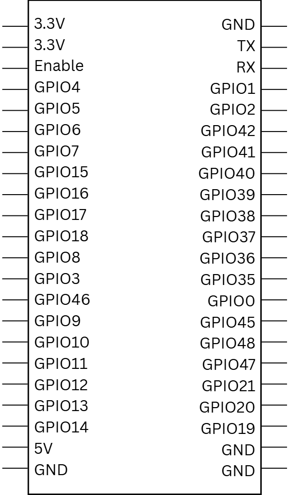
Pin Configuration and Descriptions

The ESP32S3 has a flexible pinout, with GPIO pins that can be configured for multiple functions. Below is a table summarizing the key pins:

Pin Name Function Description
GPIO0 Input/Output, Boot Mode Used for boot mode selection during startup.
GPIO1-45 General Purpose I/O Configurable for digital I/O, ADC, DAC, PWM, I2C, SPI, UART, etc.
EN Enable Chip enable pin. Pull high to enable the chip.
3V3 Power Supply 3.3V power input.
GND Ground Ground connection.
TXD0/RXD0 UART0 TX/RX Default UART for serial communication.
ADC1/ADC2 Analog Input 12-bit ADC channels for analog signal input.
DAC1/DAC2 Digital-to-Analog Converter 8-bit DAC channels for analog signal output.
SPI Pins SPI Communication Includes MOSI, MISO, SCLK, and CS for SPI communication.
I2C Pins I2C Communication Includes SDA and SCL for I2C communication.

Note: The exact pinout may vary depending on the specific ESP32S3 module or development board being used.

Usage Instructions

The ESP32S3 can be used in a variety of circuits and applications. Below are the steps and best practices for using the ESP32S3 in your projects.

Basic Setup

  1. Power Supply: Ensure the ESP32S3 is powered with a stable 3.3V supply. Avoid exceeding the maximum voltage of 3.6V.
  2. Boot Mode: To upload code, connect GPIO0 to GND during reset to enter bootloader mode.
  3. Programming: Use the ESP-IDF (Espressif IoT Development Framework) or Arduino IDE for programming the ESP32S3.

Example: Connecting to Wi-Fi with Arduino IDE

The following example demonstrates how to connect the ESP32S3 to a Wi-Fi network using the Arduino IDE:

#include <WiFi.h> // Include the Wi-Fi library for ESP32

// Replace with your network credentials
const char* ssid = "Your_SSID";       // Your Wi-Fi network name
const char* password = "Your_PASSWORD"; // Your Wi-Fi network password

void setup() {
  Serial.begin(115200); // Initialize serial communication at 115200 baud
  delay(1000);

  Serial.println("Connecting to Wi-Fi...");
  WiFi.begin(ssid, password); // Start Wi-Fi connection

  // Wait until the ESP32S3 is connected to Wi-Fi
  while (WiFi.status() != WL_CONNECTED) {
    delay(500);
    Serial.print(".");
  }

  Serial.println("\nWi-Fi connected!");
  Serial.print("IP Address: ");
  Serial.println(WiFi.localIP()); // Print the assigned IP address
}

void loop() {
  // Add your main code here
}

Important Considerations

  • GPIO Voltage Levels: The GPIO pins are not 5V tolerant. Use level shifters if interfacing with 5V devices.
  • Power Supply: Use a low-noise, stable power source to avoid issues with Wi-Fi and BLE performance.
  • Antenna Placement: Ensure proper placement of the onboard or external antenna for optimal wireless performance.

Troubleshooting and FAQs

Common Issues and Solutions

  1. Issue: The ESP32S3 does not connect to Wi-Fi.

    • Solution: Double-check the SSID and password. Ensure the Wi-Fi network is 2.4 GHz, as the ESP32S3 does not support 5 GHz networks.
  2. Issue: The ESP32S3 is not detected by the computer.

    • Solution: Ensure the correct USB driver is installed. Use a data-capable USB cable and verify the connection.
  3. Issue: GPIO pins are not functioning as expected.

    • Solution: Verify the pin configuration in your code. Ensure no conflicting peripherals are assigned to the same pin.
  4. Issue: High power consumption in battery-powered applications.

    • Solution: Use the ESP32S3's deep sleep mode to reduce power consumption. Refer to the ESP-IDF documentation for details.

FAQs

  • Q: Can the ESP32S3 be used with the Arduino IDE?

    • A: Yes, the ESP32S3 is fully supported in the Arduino IDE. Install the ESP32 board package to get started.
  • Q: Does the ESP32S3 support Bluetooth Classic?

    • A: No, the ESP32S3 supports Bluetooth Low Energy (BLE) 5.0 but does not support Bluetooth Classic.
  • Q: What is the maximum range of the ESP32S3's Wi-Fi?

    • A: The range depends on environmental factors, but typically it can reach up to 100 meters in open spaces.
  • Q: Can I use external flash or PSRAM with the ESP32S3?

    • A: Yes, the ESP32S3 supports external SPI flash and PSRAM for additional storage and memory.

This concludes the documentation for the ESP32S3. For more details, refer to the official ESP32S3 datasheet and technical reference manual.