How to Use L293D Driver Shield: Examples, Pinouts, and Specs
Introduction
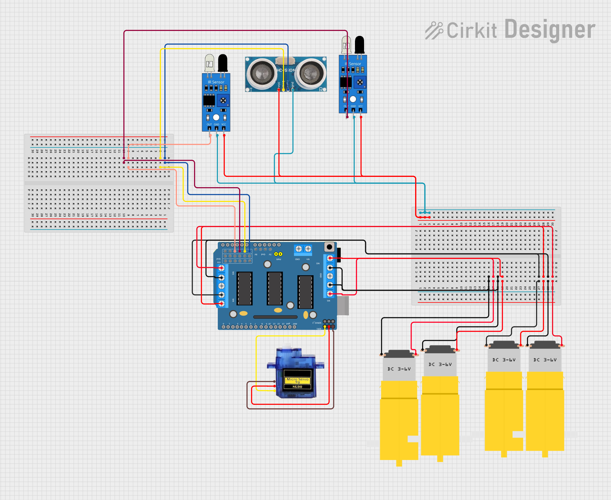
The L293D Driver Shield is an essential component for hobbyists and engineers alike, providing the ability to control the speed and direction of DC motors with ease. This motor driver IC is designed to drive inductive loads such as relays, solenoids, and DC and bipolar stepping motors. It's a popular choice for robotics, automated machinery, and a variety of DIY projects where motor control is required.
Explore Projects Built with L293D Driver Shield
Explore Projects Built with L293D Driver Shield
Common Applications and Use Cases
- Robotics: Steering and propulsion systems.
- Automated machinery: Conveyor belts, pulley systems.
- Hobby projects: Remote-controlled vehicles, automated art installations.
- Educational purposes: Learning about motor control and automation.
Technical Specifications
Key Technical Details
- Supply Voltage (Vcc1): 4.5V to 36V
- Supply Voltage for Motors (Vcc2): 4.5V to 36V
- Peak Output Current (per channel): 1.2A
- Continuous Output Current (per channel): 600mA
- Maximum Power Dissipation: 4W
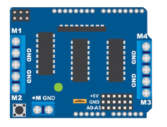
Pin Configuration and Descriptions
| Pin Number | Pin Name | Description |
|---|---|---|
| 1 | 1,2EN | Enable pin for Motor 1 and 2 |
| 2 | 1A | Input 1 for Motor 1 |
| 3 | 1Y | Output 1 for Motor 1 |
| 4 | GND | Ground |
| 5 | GND | Ground |
| 6 | 2Y | Output 2 for Motor 1 |
| 7 | 2A | Input 2 for Motor 1 |
| 8 | Vcc2 | Motor Supply Voltage |
| 16 | Vcc1 | Logic Supply Voltage |
| 9 | 3,4EN | Enable pin for Motor 2 |
| 10 | 3A | Input 1 for Motor 2 |
| 11 | 3Y | Output 1 for Motor 2 |
| 12 | GND | Ground |
| 13 | GND | Ground |
| 14 | 4Y | Output 2 for Motor 2 |
| 15 | 4A | Input 2 for Motor 2 |
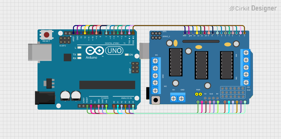
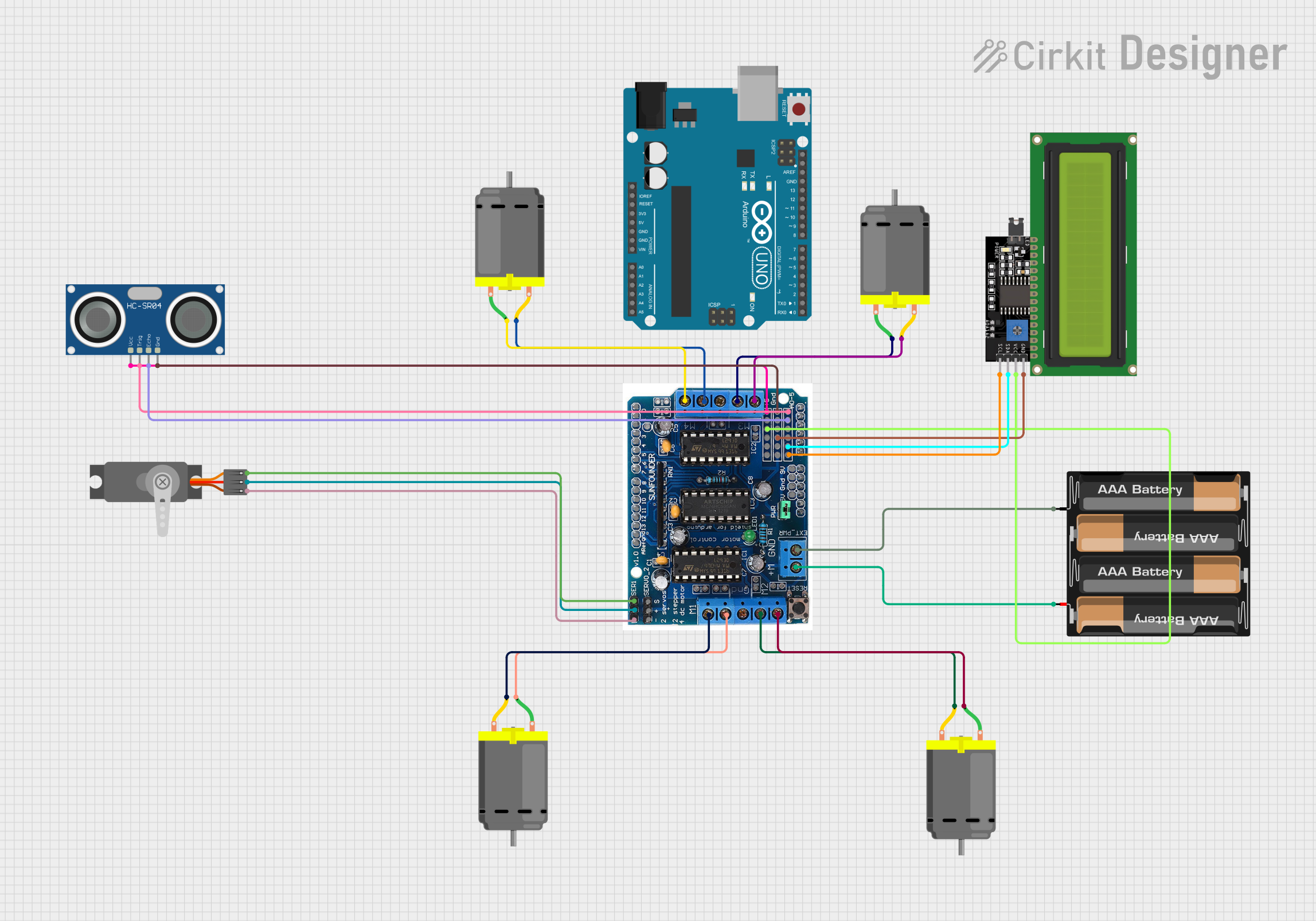
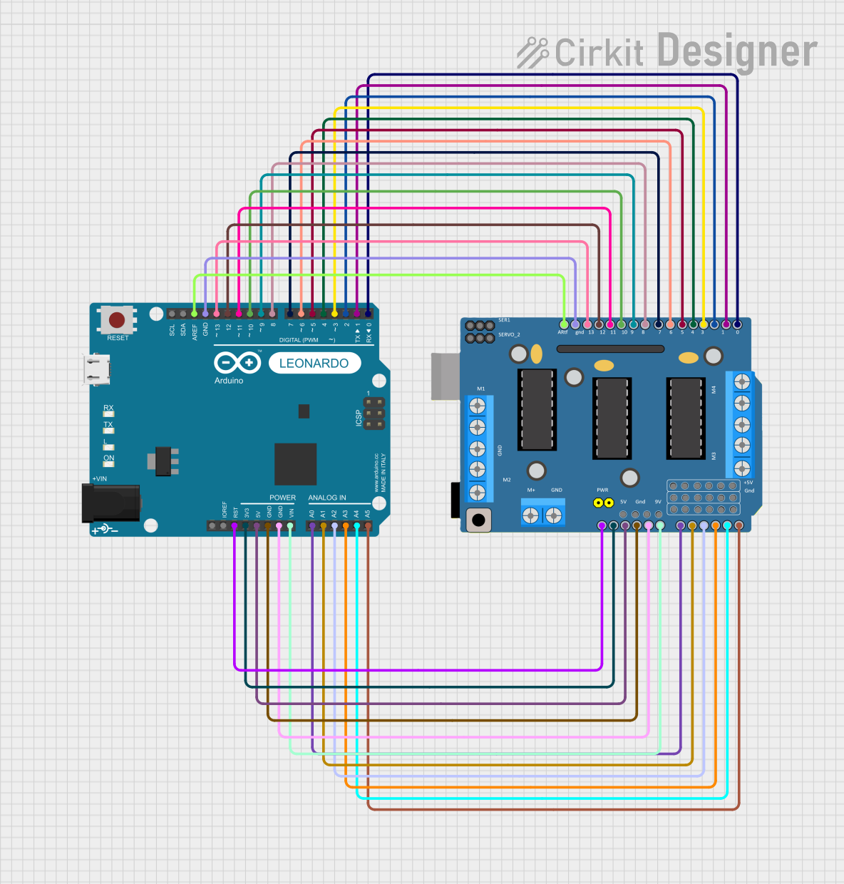
Usage Instructions
How to Use the Component in a Circuit
Connecting Power:
- Connect Vcc1 to a 5V supply for the logic circuit.
- Connect Vcc2 to the motor power supply, which can range from 4.5V to 36V.
Connecting Motors:
- Connect your DC motor leads to the output pins (1Y and 2Y for Motor 1, 3Y and 4Y for Motor 2).
Control Signals:
- Apply high or low logic levels to the input pins (1A, 2A for Motor 1, 3A, 4A for Motor 2) to control the motor direction.
- Use the enable pins (1,2EN for Motor 1, 3,4EN for Motor 2) to start or stop the motor.
Microcontroller Interface:
- Connect the input and enable pins to the corresponding digital output pins on your microcontroller or Arduino UNO.
Important Considerations and Best Practices
- Ensure that the power supply voltage does not exceed the specified limits for Vcc1 and Vcc2.
- Always use a decoupling capacitor close to the L293D's power pins to filter out noise and voltage spikes.
- Avoid running motors at the peak output current for extended periods to prevent thermal shutdown.
- Use heat sinks if operating near the maximum power dissipation limits.
Example Code for Arduino UNO
// Define motor control and enable pins
int motor1Pin1 = 3; // Input 1 for Motor 1
int motor1Pin2 = 4; // Input 2 for Motor 1
int enablePin1 = 9; // Enable pin for Motor 1

void setup() {
  // Set motor control pins as outputs
  pinMode(motor1Pin1, OUTPUT);
  pinMode(motor1Pin2, OUTPUT);
  pinMode(enablePin1, OUTPUT);

  // Start with the motor stopped
  digitalWrite(enablePin1, LOW);
}

void loop() {
  // Spin motor in one direction
  digitalWrite(motor1Pin1, HIGH);
  digitalWrite(motor1Pin2, LOW);
  digitalWrite(enablePin1, HIGH);
  delay(2000);

  // Stop the motor
  digitalWrite(enablePin1, LOW);
  delay(1000);

  // Spin motor in the opposite direction
  digitalWrite(motor1Pin1, LOW);
  digitalWrite(motor1Pin2, HIGH);
  digitalWrite(enablePin1, HIGH);
  delay(2000);

  // Stop the motor
  digitalWrite(enablePin1, LOW);
  delay(1000);
}
Troubleshooting and FAQs
Common Issues
- Motor not running: Check power supply connections, ensure enable pin is set high.
- Motor running weakly: Verify that the power supply can deliver sufficient current.
- Overheating: Ensure proper heat sinking and avoid prolonged operation at peak current.
Solutions and Tips for Troubleshooting
- Double-check wiring against the pin configuration table.
- Use a multimeter to verify the presence of voltage at the motor outputs when enabled.
- Ensure that the logic inputs are receiving the correct signals from the microcontroller.
FAQs
Q: Can the L293D drive stepper motors? A: Yes, the L293D can drive bipolar stepper motors with proper control sequences.
Q: What is the maximum current the L293D can handle? A: The L293D can handle up to 1.2A peak per channel or 600mA continuous per channel.
Q: Can I control the speed of the motors using the L293D? A: Yes, you can control the speed by applying PWM signals to the enable pins.
Q: Do I need external diodes for flyback protection? A: No, the L293D has built-in flyback diodes for protection against inductive voltage spikes.