Cirkit Designer Logo
Cirkit Designer
Your all-in-one circuit design IDE
Home / 
Component Documentation

How to Use Yellow Geared Motor with Encoder: Examples, Pinouts, and Specs

Image of Yellow Geared Motor with Encoder
Cirkit Designer LogoDesign with Yellow Geared Motor with Encoder in Cirkit Designer

Introduction

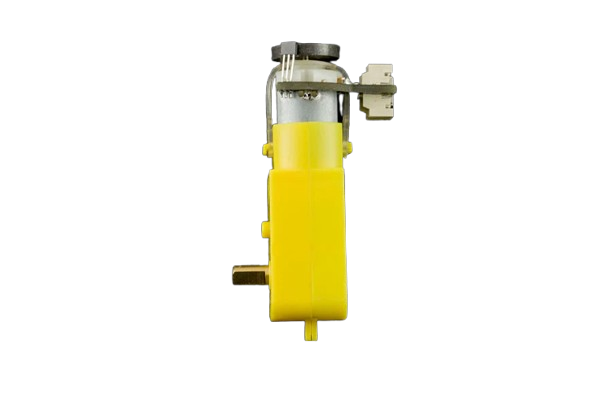
The Yellow Geared Motor with Encoder (Manufacturer Part ID: FIT0450) by DFRobot Accessories is a compact and versatile motor designed for robotics and automation applications. It combines a gear mechanism for torque amplification and an encoder for precise position and speed feedback. This motor is ideal for projects requiring controlled motion, such as robotic arms, wheeled robots, and conveyor systems.

Explore Projects Built with Yellow Geared Motor with Encoder

Use Cirkit Designer to design, explore, and prototype these projects online. Some projects support real-time simulation. Click "Open Project" to start designing instantly!
Arduino-Controlled DC Motor with Encoder Feedback and Adjustable Speed
Image of gear motor: A project utilizing Yellow Geared Motor with Encoder in a practical application
This circuit controls a gear motor with an integrated encoder using an L298N DC motor driver, which is interfaced with an Arduino Mega 2560 microcontroller. The motor's power is supplied by a 12V power source, which is also connected to an XL4015 DC Buck Step-down converter to provide a regulated 5V supply to the Arduino. The encoder outputs are connected to the Arduino for position or speed feedback, and the Arduino is programmed to manage the motor's speed and direction.
Cirkit Designer LogoOpen Project in Cirkit Designer
Arduino UNO Controlled Gear Motor and Servo System with Integrated Encoder
Image of circuit électrique global de la plateforme : A project utilizing Yellow Geared Motor with Encoder in a practical application
This circuit controls a gear motor with an integrated encoder and a servo motor using an Arduino UNO. The Arduino reads encoder signals to measure the motor's speed and direction, and it can control the motor's speed and direction via a Cytron MD-10 motor driver. Additionally, the Arduino controls the position of a servo motor.
Cirkit Designer LogoOpen Project in Cirkit Designer
Arduino-Controlled Robotic System with Servos, Ultrasonic Sensors, and Gear Motor
Image of integrated circuit: A project utilizing Yellow Geared Motor with Encoder in a practical application
This circuit is designed to control a gear motor with an integrated encoder and a servo motor, using an Arduino UNO as the central microcontroller. It includes an L298N motor driver to drive the gear motor, and multiple HC-SR04 ultrasonic sensors for distance measurement. The circuit is powered by a 12V power supply, regulated down to 5V by an XL4015 DC-DC buck converter to power the Arduino and other 5V components.
Cirkit Designer LogoOpen Project in Cirkit Designer
Arduino Mega 2560 Controlled Motor with Rotary Encoder Feedback
Image of Motor Control via Encoder: A project utilizing Yellow Geared Motor with Encoder in a practical application
This circuit uses an Arduino Mega 2560 to control a hobby gear motor via an L293D motor driver, with a rotary encoder providing feedback. The Arduino reads the encoder signals to determine the motor's position and speed, and adjusts the motor's operation accordingly.
Cirkit Designer LogoOpen Project in Cirkit Designer

Explore Projects Built with Yellow Geared Motor with Encoder

Use Cirkit Designer to design, explore, and prototype these projects online. Some projects support real-time simulation. Click "Open Project" to start designing instantly!
Image of gear motor: A project utilizing Yellow Geared Motor with Encoder in a practical application
Arduino-Controlled DC Motor with Encoder Feedback and Adjustable Speed
This circuit controls a gear motor with an integrated encoder using an L298N DC motor driver, which is interfaced with an Arduino Mega 2560 microcontroller. The motor's power is supplied by a 12V power source, which is also connected to an XL4015 DC Buck Step-down converter to provide a regulated 5V supply to the Arduino. The encoder outputs are connected to the Arduino for position or speed feedback, and the Arduino is programmed to manage the motor's speed and direction.
Cirkit Designer LogoOpen Project in Cirkit Designer
Image of circuit électrique global de la plateforme : A project utilizing Yellow Geared Motor with Encoder in a practical application
Arduino UNO Controlled Gear Motor and Servo System with Integrated Encoder
This circuit controls a gear motor with an integrated encoder and a servo motor using an Arduino UNO. The Arduino reads encoder signals to measure the motor's speed and direction, and it can control the motor's speed and direction via a Cytron MD-10 motor driver. Additionally, the Arduino controls the position of a servo motor.
Cirkit Designer LogoOpen Project in Cirkit Designer
Image of integrated circuit: A project utilizing Yellow Geared Motor with Encoder in a practical application
Arduino-Controlled Robotic System with Servos, Ultrasonic Sensors, and Gear Motor
This circuit is designed to control a gear motor with an integrated encoder and a servo motor, using an Arduino UNO as the central microcontroller. It includes an L298N motor driver to drive the gear motor, and multiple HC-SR04 ultrasonic sensors for distance measurement. The circuit is powered by a 12V power supply, regulated down to 5V by an XL4015 DC-DC buck converter to power the Arduino and other 5V components.
Cirkit Designer LogoOpen Project in Cirkit Designer
Image of Motor Control via Encoder: A project utilizing Yellow Geared Motor with Encoder in a practical application
Arduino Mega 2560 Controlled Motor with Rotary Encoder Feedback
This circuit uses an Arduino Mega 2560 to control a hobby gear motor via an L293D motor driver, with a rotary encoder providing feedback. The Arduino reads the encoder signals to determine the motor's position and speed, and adjusts the motor's operation accordingly.
Cirkit Designer LogoOpen Project in Cirkit Designer

Common Applications

  • Robotics (e.g., mobile robots, robotic arms)
  • Automated conveyor systems
  • Precision motion control in DIY projects
  • Educational and prototyping purposes

Technical Specifications

Below are the key technical details of the Yellow Geared Motor with Encoder:

Parameter Value
Operating Voltage 3V - 6V DC
Rated Voltage 6V DC
No-Load Speed 150 RPM (at 6V)
Stall Torque 1.5 kg·cm (at 6V)
Stall Current 0.8 A (at 6V)
Gear Ratio 1:48
Encoder Resolution 11 pulses per revolution (PPR)
Shaft Diameter 5.5 mm
Motor Dimensions 70 mm x 22 mm x 18 mm
Weight 45 g

Pin Configuration and Descriptions

The motor comes with a 4-pin connector for the encoder and two terminals for the motor power. Below is the pinout:

Motor Power Terminals

Terminal Description
+ Positive motor terminal
- Negative motor terminal

Encoder Pinout

Pin Wire Color Description
VCC Red Power supply for the encoder (3.3V-5V)
GND Black Ground
A Yellow Encoder output channel A
B Green Encoder output channel B

Usage Instructions

How to Use the Component in a Circuit

  1. Powering the Motor: Connect the motor terminals to a DC power supply or motor driver. Ensure the voltage does not exceed 6V to avoid damage.
  2. Connecting the Encoder:
    • Connect the VCC and GND pins of the encoder to a 3.3V or 5V power source.
    • Connect the A and B pins to the digital input pins of a microcontroller (e.g., Arduino UNO) to read encoder signals.
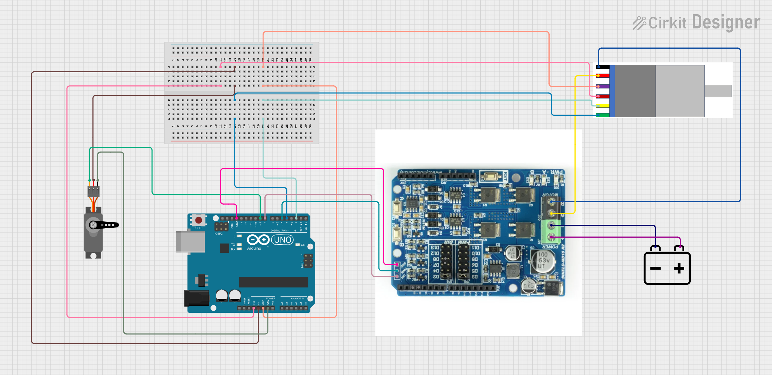
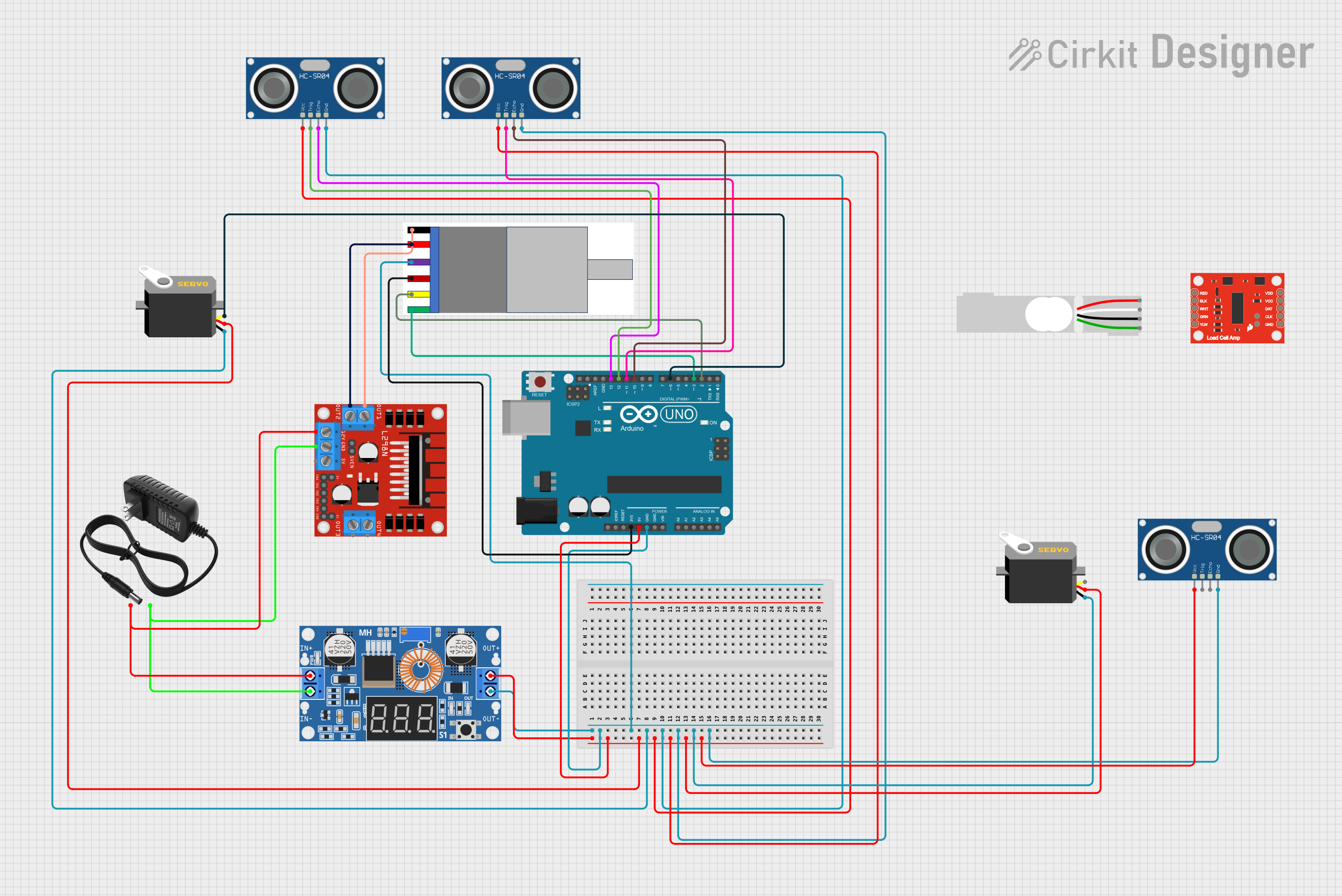
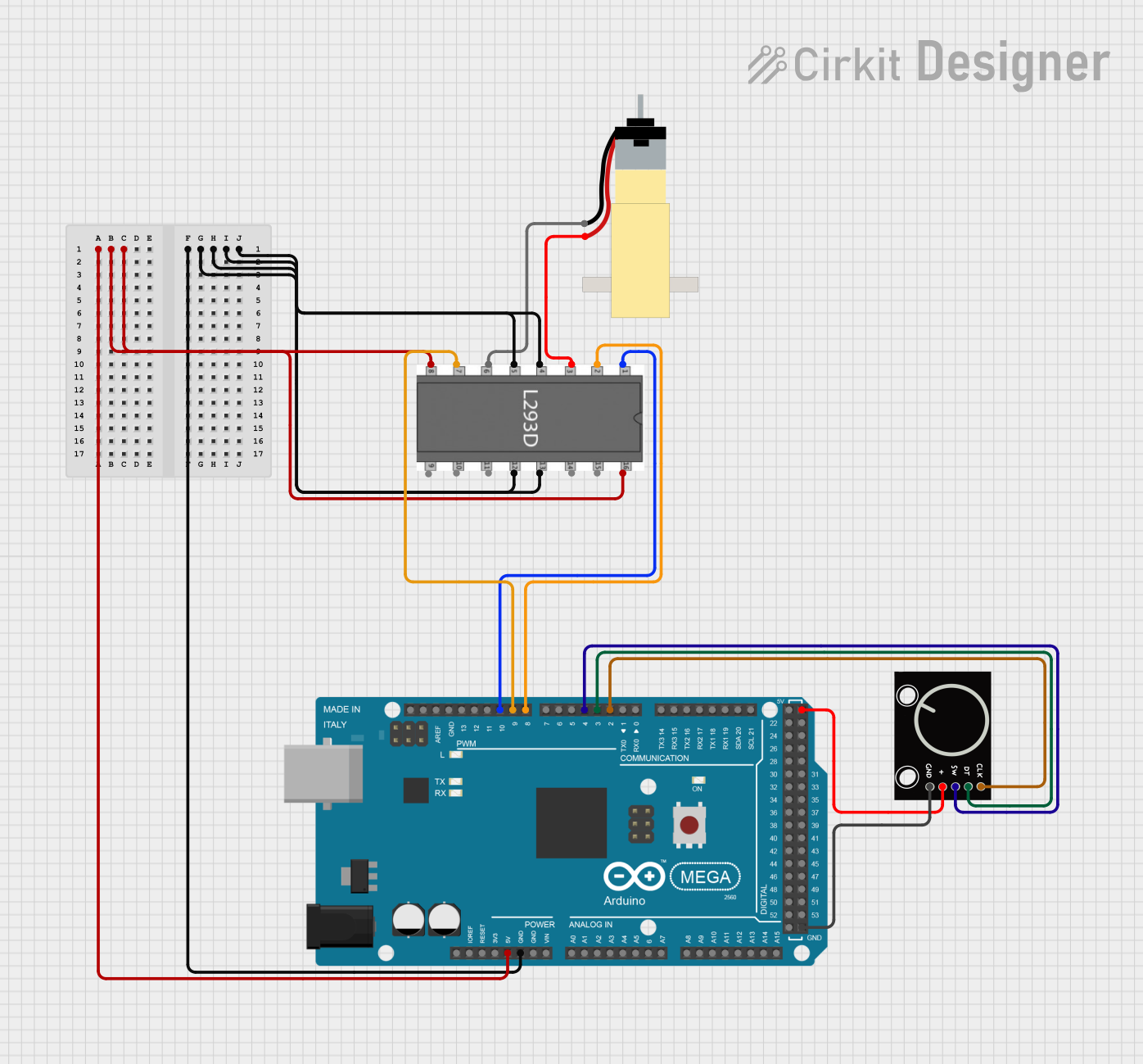
  3. Motor Driver: Use an H-bridge motor driver (e.g., L298N or L293D) to control the motor's direction and speed.

Important Considerations and Best Practices

  • Voltage Limits: Operate the motor within the specified voltage range (3V-6V) to prevent overheating or damage.
  • Current Requirements: Ensure your power supply or motor driver can handle the stall current (0.8A at 6V).
  • Encoder Signal Handling: Use pull-up resistors if the encoder signals are unstable.
  • Mounting: Secure the motor properly to avoid vibrations that may affect encoder readings.

Example: Using with Arduino UNO

Below is an example of how to connect and use the motor with an Arduino UNO to read encoder signals and control the motor:

Circuit Connections

  • Connect the motor terminals to an H-bridge motor driver.
  • Connect the encoder pins as follows:
    • VCC to Arduino 5V
    • GND to Arduino GND
    • A to Arduino digital pin 2
    • B to Arduino digital pin 3

Arduino Code

// Define encoder pins
const int encoderPinA = 2; // Channel A connected to digital pin 2
const int encoderPinB = 3; // Channel B connected to digital pin 3

volatile int encoderCount = 0; // Variable to store encoder count

void setup() {
  pinMode(encoderPinA, INPUT); // Set encoder pin A as input
  pinMode(encoderPinB, INPUT); // Set encoder pin B as input

  // Attach interrupt to encoder pin A
  attachInterrupt(digitalPinToInterrupt(encoderPinA), encoderISR, CHANGE);

  Serial.begin(9600); // Initialize serial communication
}

void loop() {
  // Print the encoder count to the Serial Monitor
  Serial.print("Encoder Count: ");
  Serial.println(encoderCount);
  delay(100); // Delay for readability
}

// Interrupt Service Routine (ISR) for encoder
void encoderISR() {
  // Read the state of channel B
  int stateB = digitalRead(encoderPinB);

  // Determine direction based on channel B state
  if (stateB == HIGH) {
    encoderCount++; // Increment count for forward rotation
  } else {
    encoderCount--; // Decrement count for reverse rotation
  }
}

Notes:

  • The encoder count can be used to calculate the motor's position or speed.
  • Use a motor driver to control the motor's speed and direction.

Troubleshooting and FAQs

Common Issues

  1. Motor Not Spinning:

    • Cause: Insufficient power supply or incorrect wiring.
    • Solution: Verify the power supply voltage and check the motor connections.
  2. Encoder Not Providing Signals:

    • Cause: Incorrect wiring or insufficient power to the encoder.
    • Solution: Ensure the encoder VCC and GND are connected properly, and check the connections to the microcontroller.
  3. Unstable Encoder Readings:

    • Cause: Electrical noise or lack of pull-up resistors.
    • Solution: Add pull-up resistors to the encoder signal lines and ensure proper grounding.
  4. Motor Overheating:

    • Cause: Operating the motor beyond its voltage or current limits.
    • Solution: Use a power supply within the specified range and avoid prolonged stall conditions.

FAQs

Q: Can I use this motor with a 12V power supply?
A: No, the motor is rated for a maximum of 6V. Using a higher voltage may damage the motor.

Q: How do I calculate the motor's speed using the encoder?
A: Measure the time between encoder pulses and use the gear ratio and encoder resolution to calculate the speed.

Q: Can I use this motor without the encoder?
A: Yes, the motor can be used without the encoder for simple applications where position or speed feedback is not required.