How to Use BlueSMiRF v2: Examples, Pinouts, and Specs
Introduction
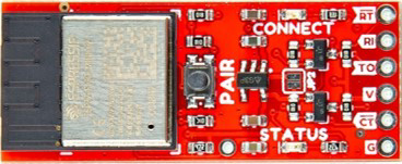
The BlueSMiRF v2 is a Bluetooth serial module designed for wireless communication, enabling devices to connect and transmit data seamlessly over Bluetooth. It acts as a bridge between embedded systems and Bluetooth-enabled devices, making it an ideal choice for applications requiring remote control, data logging, or wireless communication. Its compact design and ease of integration make it popular in robotics, IoT devices, and other embedded systems.
Explore Projects Built with BlueSMiRF v2


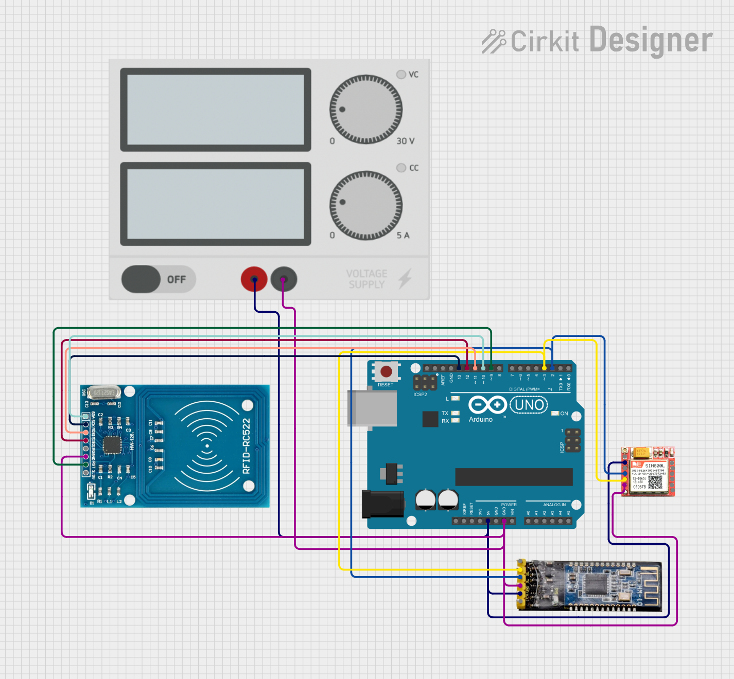
Explore Projects Built with BlueSMiRF v2
Common Applications
- Wireless communication in robotics and drones
- IoT devices for remote monitoring and control
- Serial communication with microcontrollers (e.g., Arduino, Raspberry Pi)
- Data logging and transfer in embedded systems
- Wireless debugging and programming
Technical Specifications
Key Technical Details
| Parameter | Value |
|---|---|
| Bluetooth Version | Bluetooth 2.0 + EDR |
| Communication Protocol | UART (Serial) |
| Baud Rate | Configurable (Default: 115200) |
| Operating Voltage | 3.3V to 6V |
| Current Consumption | 25mA (typical) |
| Range | Up to 100 meters (line of sight) |
| Dimensions | 1.75" x 0.65" (44.45mm x 16.51mm) |
| Operating Temperature | -40°C to +85°C |
Pin Configuration and Descriptions
The BlueSMiRF v2 has a simple pinout for easy integration into circuits. Below is the pin configuration:
| Pin Name | Description |
|---|---|
| VCC | Power input (3.3V to 6V). Provides power to the module. |
| GND | Ground. Connect to the ground of the circuit. |
| TX-OUT | Transmit pin. Sends serial data from the module to the connected device. |
| RX-IN | Receive pin. Receives serial data from the connected device. |
| CTS | Clear to Send. Used for hardware flow control (optional). |
| RTS | Ready to Send. Used for hardware flow control (optional). |
Usage Instructions
How to Use the BlueSMiRF v2 in a Circuit
- Power the Module: Connect the
VCCpin to a 3.3V to 6V power source and theGNDpin to the ground of your circuit. - Connect Serial Pins:
- Connect the
TX-OUTpin of the BlueSMiRF to theRXpin of your microcontroller. - Connect the
RX-INpin of the BlueSMiRF to theTXpin of your microcontroller.
- Connect the
- Optional Flow Control: If hardware flow control is required, connect the
CTSandRTSpins to the corresponding pins on your microcontroller. - Pairing: The module will appear as a Bluetooth device on your computer or smartphone. Pair with the module using the default passcode (
1234). - Communication: Use a serial terminal or microcontroller code to send and receive data over Bluetooth.
Important Considerations
- Voltage Levels: Ensure that the
RX-INpin does not receive voltages higher than 3.3V. Use a voltage divider or level shifter if interfacing with a 5V microcontroller. - Baud Rate: The default baud rate is 115200. Configure your microcontroller or terminal software to match this baud rate.
- Range: The module's range is up to 100 meters in line-of-sight conditions. Obstacles like walls may reduce the range.
- Antenna Orientation: For optimal performance, ensure the module's antenna is not obstructed by metal or other materials.
Example: Connecting to an Arduino UNO
Below is an example of how to use the BlueSMiRF v2 with an Arduino UNO for wireless communication.
Circuit Connections
VCC→ 5V on ArduinoGND→ GND on ArduinoTX-OUT→ RX (Pin 0) on ArduinoRX-IN→ TX (Pin 1) on Arduino
Arduino Code
#include <SoftwareSerial.h>

// Define RX and TX pins for SoftwareSerial
SoftwareSerial bluetooth(10, 11); // RX = Pin 10, TX = Pin 11

void setup() {
  // Start the hardware serial communication for debugging
  Serial.begin(9600);
  // Start the Bluetooth serial communication
  bluetooth.begin(115200); // Default baud rate for BlueSMiRF v2
  Serial.println("Bluetooth module ready. Waiting for data...");
}

void loop() {
  // Check if data is available from the Bluetooth module
  if (bluetooth.available()) {
    char data = bluetooth.read(); // Read a character from Bluetooth
    Serial.print("Received: ");
    Serial.println(data); // Print the received data to the Serial Monitor
  }

  // Check if data is available from the Serial Monitor
  if (Serial.available()) {
    char data = Serial.read(); // Read a character from Serial Monitor
    bluetooth.write(data); // Send the data to the Bluetooth module
    Serial.print("Sent: ");
    Serial.println(data); // Print the sent data to the Serial Monitor
  }
}
Notes
- Use
SoftwareSerialif the hardware serial pins (0 and 1) are already in use. - Ensure the baud rate in the code matches the module's configured baud rate.
Troubleshooting and FAQs
Common Issues and Solutions
Module Not Pairing
- Ensure the module is powered and in range.
- Check if the module is discoverable (LED should blink rapidly).
- Verify the default passcode (
1234) during pairing.
No Data Transmission
- Confirm the
TXandRXpins are correctly connected. - Check the baud rate settings on both the module and the microcontroller.
- Ensure the
RX-INpin voltage does not exceed 3.3V.
- Confirm the
Limited Range
- Ensure there are no significant obstacles between the module and the paired device.
- Check the antenna orientation and avoid placing the module near metal objects.
Unstable Connection
- Verify the power supply is stable and within the specified voltage range.
- Reduce the baud rate if experiencing data loss.
FAQs
Q: Can the BlueSMiRF v2 work with a 5V microcontroller?
A: Yes, but you must use a voltage divider or level shifter to ensure the RX-IN pin does not exceed 3.3V.
Q: How do I change the baud rate of the module?
A: Use AT commands to configure the baud rate. Refer to the module's AT command documentation for details.
Q: Can I use the module for audio transmission?
A: No, the BlueSMiRF v2 is designed for serial data communication and does not support audio transmission.
Q: What is the default name of the module?
A: The default name is typically "BlueSMiRF" or "RN-42". You can change it using AT commands.
By following this documentation, you can effectively integrate the BlueSMiRF v2 into your projects for reliable wireless communication.