Cirkit Designer
Your all-in-one circuit design IDE
Home /
Component Documentation
How to Use Deneyap Kart: Examples, Pinouts, and Specs
Deneyap Kart Documentation
1. Introduction
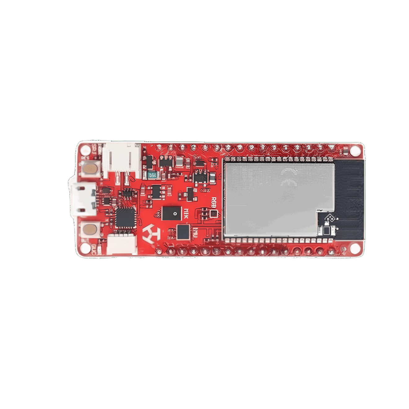
The Deneyap Kart, manufactured by ROBOLİG (KOKBORU), is a versatile microcontroller development board designed for educational purposes. It features a variety of input/output pins, sensors, and connectivity options, making it an excellent tool for learning and prototyping in electronics and programming.
Common Applications and Use Cases
- Educational Projects: Ideal for students and educators to learn about microcontrollers, sensors, and basic electronics.
- Prototyping: Suitable for hobbyists and engineers to quickly prototype and test new ideas.
- IoT Projects: With built-in connectivity options, it can be used for Internet of Things (IoT) applications.
- Robotics: Can be integrated into robotic systems for control and automation.
2. Technical Specifications
Key Technical Details
| Specification | Value |
|---|---|
| Microcontroller | ARM Cortex-M4 |
| Operating Voltage | 3.3V |
| Input Voltage | 5V via USB, 7-12V via VIN pin |
| Digital I/O Pins | 14 (of which 6 provide PWM) |
| Analog Input Pins | 6 |
| Flash Memory | 256 KB |
| SRAM | 32 KB |
| Clock Speed | 72 MHz |
| Connectivity | Wi-Fi, Bluetooth |
| Dimensions | 68.6 mm x 53.4 mm |
Pin Configuration and Descriptions
| Pin Number | Pin Name | Description |
|---|---|---|
| 1 | VIN | Input voltage (7-12V) |
| 2 | GND | Ground |
| 3 | 3.3V | 3.3V output |
| 4 | 5V | 5V output |
| 5 | A0 | Analog input 0 |
| 6 | A1 | Analog input 1 |
| 7 | A2 | Analog input 2 |
| 8 | A3 | Analog input 3 |
| 9 | A4 | Analog input 4 |
| 10 | A5 | Analog input 5 |
| 11 | D0 | Digital I/O 0 |
| 12 | D1 | Digital I/O 1 |
| 13 | D2 | Digital I/O 2 |
| 14 | D3 | Digital I/O 3 (PWM) |
| 15 | D4 | Digital I/O 4 |
| 16 | D5 | Digital I/O 5 (PWM) |
| 17 | D6 | Digital I/O 6 (PWM) |
| 18 | D7 | Digital I/O 7 |
| 19 | D8 | Digital I/O 8 |
| 20 | D9 | Digital I/O 9 (PWM) |
| 21 | D10 | Digital I/O 10 (PWM) |
| 22 | D11 | Digital I/O 11 (PWM) |
| 23 | D12 | Digital I/O 12 |
| 24 | D13 | Digital I/O 13 |
| 25 | RX | UART Receive |
| 26 | TX | UART Transmit |
| 27 | SDA | I2C Data |
| 28 | SCL | I2C Clock |
| 29 | MOSI | SPI Master Out Slave In |
| 30 | MISO | SPI Master In Slave Out |
| 31 | SCK | SPI Clock |
| 32 | RST | Reset |
3. Usage Instructions
How to Use the Deneyap Kart in a Circuit
Powering the Board:
- Connect the board to a computer via USB for power and programming.
- Alternatively, use the VIN pin to supply 7-12V from an external power source.
Connecting Sensors and Actuators:
- Use the digital I/O pins (D0-D13) to connect digital sensors and actuators.
- Use the analog input pins (A0-A5) to connect analog sensors.
Programming the Board:
- Use the Arduino IDE to write and upload code to the Deneyap Kart.
- Select the appropriate board and port from the Arduino IDE.
Important Considerations and Best Practices
- Voltage Levels: Ensure that the input voltage does not exceed the specified range to avoid damaging the board.
- Pin Usage: Be mindful of the pin configurations and avoid conflicts, especially when using multiple peripherals.
- Code Optimization: Write efficient code to make the best use of the available memory and processing power.
Sample Code for Arduino UNO
// Sample code to blink an LED connected to pin D13

void setup() {
  pinMode(13, OUTPUT); // Set pin D13 as an output
}

void loop() {
  digitalWrite(13, HIGH); // Turn the LED on
  delay(1000);            // Wait for 1 second
  digitalWrite(13, LOW);  // Turn the LED off
  delay(1000);            // Wait for 1 second
}
4. Troubleshooting and FAQs
Common Issues Users Might Face
Board Not Recognized by Computer:
- Ensure the USB cable is properly connected.
- Check if the correct drivers are installed.
Code Not Uploading:
- Verify that the correct board and port are selected in the Arduino IDE.
- Ensure no other application is using the COM port.
Sensors Not Working:
- Double-check the wiring and connections.
- Ensure the sensors are compatible with the operating voltage of the board.
Solutions and Tips for Troubleshooting
- Reset the Board: Press the reset button to restart the microcontroller.
- Check Power Supply: Ensure the board is receiving adequate power.
- Use Serial Monitor: Utilize the Serial Monitor in the Arduino IDE to debug and print error messages.
By following this documentation, users can effectively utilize the Deneyap Kart for various educational and prototyping projects. Whether you are a beginner or an experienced user, this guide provides the necessary information to get started and troubleshoot common issues.
Explore Projects Built with Deneyap Kart
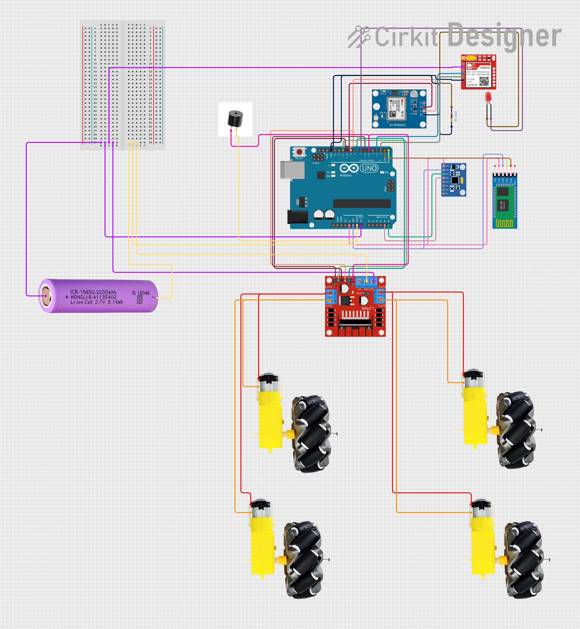
WiFi-Controlled Basket-Carrying Robot with GPS and GSM Notification

This circuit is designed for a 4-wheeled WiFi-controlled car with a basket, which uses an ESP8266 NodeMCU microcontroller for logic control. It features an IR sensor for basket full detection, a GPS module for location tracking, and a GSM module (Sim800l) for sending SMS notifications. The L298N motor driver controls four DC gearmotors for movement, and the system is powered by a Li-ion battery with a 7805 voltage regulator providing stable power to the GSM module.
Arduino Uno Wi-Fi Controlled Rover with Ultrasonic and PIR Sensors
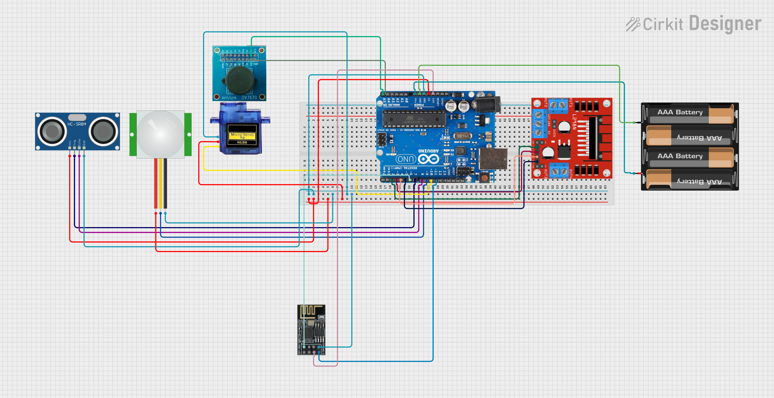
This circuit is a Wi-Fi controlled rover with obstacle detection and motion sensing capabilities. It uses an Arduino Uno to interface with an HC-SR04 ultrasonic sensor for distance measurement, a PIR sensor for motion detection, a micro servo for camera panning, and an L298N motor driver for controlling the rover's motors. The ESP8266 Wi-Fi module allows remote control via a web interface.
Arduino UNO-Based Accident Detection and Alert System with GPS and GSM
This circuit is an accident detection and alert system for a vehicle. It uses an Arduino UNO to interface with a GPS module, a GSM module, an accelerometer, and a motor driver to detect impacts, determine the vehicle's location, and send emergency alerts via SMS and calls. Additional components include a buzzer for audible alerts, a Bluetooth module for wireless communication, and an LED indicator.
Arduino-Based 4-Wheel Autonomous and Bluetooth-Controlled Car with GPS and Ultrasonic Sensors
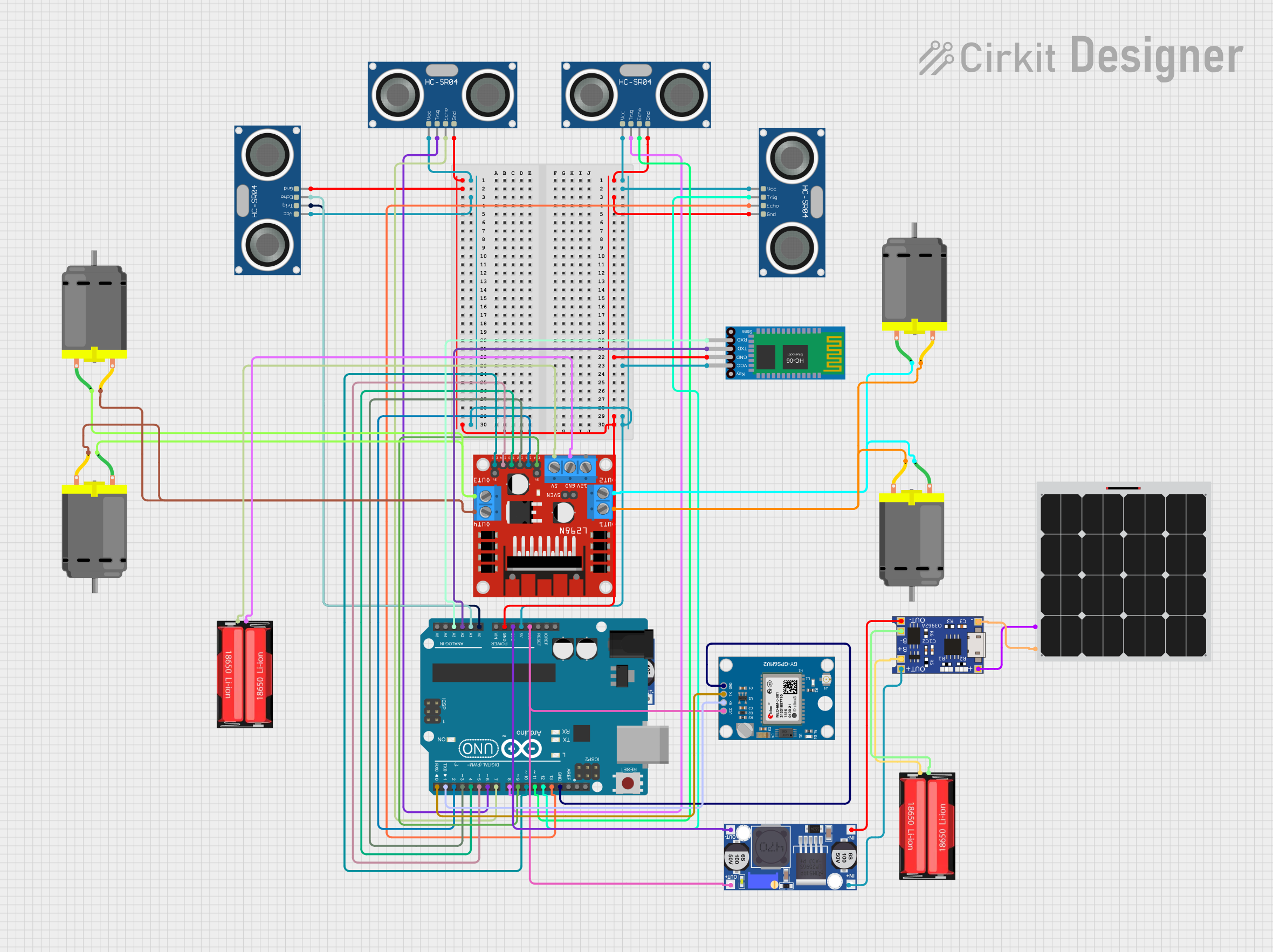
This circuit is a 4-wheel autonomous and Bluetooth-controlled car that uses an Arduino UNO to manage four DC motors via an L298N motor driver, and four HC-SR04 ultrasonic sensors for obstacle detection. It also includes a Neo 6M GPS module for tracking and a Bluetooth HC-06 module for remote control, with power supplied by a solar-charged 18650 Li-Ion battery managed through a TP4056 module and a buck converter.
Explore Projects Built with Deneyap Kart
WiFi-Controlled Basket-Carrying Robot with GPS and GSM Notification
This circuit is designed for a 4-wheeled WiFi-controlled car with a basket, which uses an ESP8266 NodeMCU microcontroller for logic control. It features an IR sensor for basket full detection, a GPS module for location tracking, and a GSM module (Sim800l) for sending SMS notifications. The L298N motor driver controls four DC gearmotors for movement, and the system is powered by a Li-ion battery with a 7805 voltage regulator providing stable power to the GSM module.
Arduino Uno Wi-Fi Controlled Rover with Ultrasonic and PIR Sensors
This circuit is a Wi-Fi controlled rover with obstacle detection and motion sensing capabilities. It uses an Arduino Uno to interface with an HC-SR04 ultrasonic sensor for distance measurement, a PIR sensor for motion detection, a micro servo for camera panning, and an L298N motor driver for controlling the rover's motors. The ESP8266 Wi-Fi module allows remote control via a web interface.
Arduino UNO-Based Accident Detection and Alert System with GPS and GSM
This circuit is an accident detection and alert system for a vehicle. It uses an Arduino UNO to interface with a GPS module, a GSM module, an accelerometer, and a motor driver to detect impacts, determine the vehicle's location, and send emergency alerts via SMS and calls. Additional components include a buzzer for audible alerts, a Bluetooth module for wireless communication, and an LED indicator.
Arduino-Based 4-Wheel Autonomous and Bluetooth-Controlled Car with GPS and Ultrasonic Sensors
This circuit is a 4-wheel autonomous and Bluetooth-controlled car that uses an Arduino UNO to manage four DC motors via an L298N motor driver, and four HC-SR04 ultrasonic sensors for obstacle detection. It also includes a Neo 6M GPS module for tracking and a Bluetooth HC-06 module for remote control, with power supplied by a solar-charged 18650 Li-Ion battery managed through a TP4056 module and a buck converter.