
How to Use Triple Axis Accelerometer Breakout - ADXL345: Examples, Pinouts, and Specs
 Design with Triple Axis Accelerometer Breakout - ADXL345 in Cirkit Designer
Introduction
The Triple Axis Accelerometer Breakout - ADXL345 by SparkFun is a compact and versatile sensor designed to measure acceleration in three axes: X, Y, and Z. It is capable of detecting both static acceleration (e.g., gravity) and dynamic acceleration (e.g., motion or vibration). With its small form factor and low power consumption, the ADXL345 is ideal for applications such as motion detection, orientation sensing, gaming devices, robotics, and wearable technology.
This breakout board simplifies interfacing with the ADXL345 sensor, making it easy to integrate into your projects. It supports both I2C and SPI communication protocols, offering flexibility for various microcontroller platforms.
Explore Projects Built with Triple Axis Accelerometer Breakout - ADXL345
 Open Project in Cirkit Designer
 Open Project in Cirkit Designer
 Open Project in Cirkit Designer
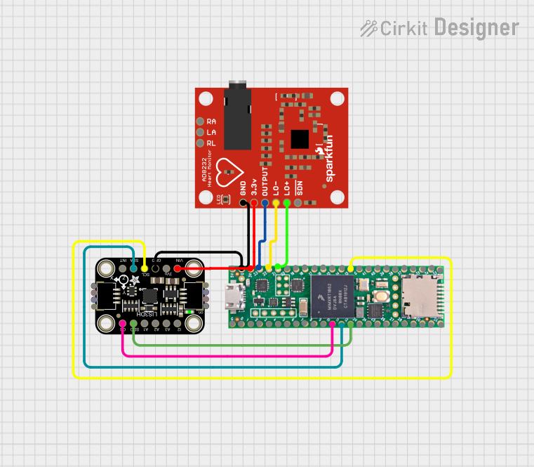 Open Project in Cirkit Designer
Explore Projects Built with Triple Axis Accelerometer Breakout - ADXL345
Open Project in Cirkit DesignerOpen Project in Cirkit DesignerOpen Project in Cirkit DesignerOpen Project in Cirkit DesignerTechnical Specifications
Key Features
- Supply Voltage: 3.3V to 5V
- Communication Protocols: I2C (up to 400kHz) and SPI (up to 10MHz)
- Measurement Range: ±2g, ±4g, ±8g, ±16g (configurable)
- Resolution: 13-bit (4mg/LSB at ±2g)
- Operating Temperature: -40°C to +85°C
- Power Consumption:
- Normal Mode: 40µA
- Standby Mode: 0.1µA
- Dimensions: 20.3mm x 20.3mm (0.8" x 0.8")
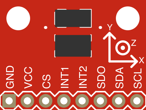
Pin Configuration and Descriptions
The breakout board has 8 pins, as described in the table below:
| Pin Name | Description |
|---|---|
| VCC | Power supply input (3.3V to 5V). |
| GND | Ground connection. |
| SDA | I2C data line (connect to microcontroller's SDA pin). |
| SCL | I2C clock line (connect to microcontroller's SCL pin). |
| CS | Chip Select for SPI communication (active low). Tie to GND for I2C mode. |
| SDO | SPI data output (or I2C address select: GND = 0x53, VCC = 0x1D). |
| SDI | SPI data input. |
| INT1 | Interrupt 1 output (configurable for motion detection, free-fall, etc.). |
Usage Instructions
Connecting the ADXL345 to an Arduino UNO
To use the ADXL345 with an Arduino UNO, follow these steps:
Wiring:
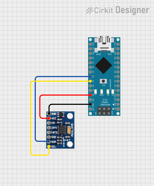
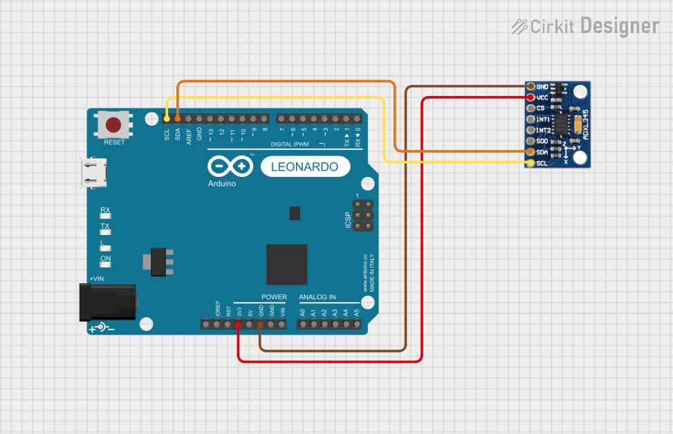
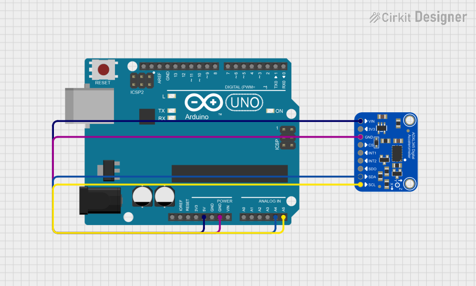
- Connect the VCC pin of the ADXL345 to the 3.3V or 5V pin on the Arduino.
- Connect the GND pin of the ADXL345 to the GND pin on the Arduino.
- Connect the SDA pin of the ADXL345 to the A4 pin on the Arduino (I2C data line).
- Connect the SCL pin of the ADXL345 to the A5 pin on the Arduino (I2C clock line).
- Tie the CS pin to GND to enable I2C mode.
- Optionally, connect the INT1 pin to a digital pin on the Arduino for interrupt-based applications.
Install Required Libraries:
- Install the "Adafruit_ADXL345" library from the Arduino Library Manager.
Example Code: Below is an example Arduino sketch to read acceleration data from the ADXL345:
#include <Wire.h>
#include <Adafruit_Sensor.h>
#include <Adafruit_ADXL345_U.h>

// Create an ADXL345 object
Adafruit_ADXL345_Unified accel = Adafruit_ADXL345_Unified(12345);

void setup() {
  Serial.begin(9600);
  // Initialize the sensor
  if (!accel.begin()) {
    Serial.println("Failed to find ADXL345 chip");
    while (1); // Halt if sensor initialization fails
  }
  Serial.println("ADXL345 initialized successfully!");

  // Set measurement range to ±4g
  accel.setRange(ADXL345_RANGE_4_G);
  Serial.println("Range set to ±4g");
}

void loop() {
  sensors_event_t event;
  accel.getEvent(&event);

  // Print acceleration data
  Serial.print("X: "); Serial.print(event.acceleration.x); Serial.print(" m/s^2 ");
  Serial.print("Y: "); Serial.print(event.acceleration.y); Serial.print(" m/s^2 ");
  Serial.print("Z: "); Serial.print(event.acceleration.z); Serial.println(" m/s^2");

  delay(500); // Delay for readability
}
Important Considerations
- Power Supply: Ensure the ADXL345 is powered within its specified voltage range (3.3V to 5V).
- Pull-Up Resistors: If using I2C, ensure pull-up resistors (typically 4.7kΩ) are present on the SDA and SCL lines. Some breakout boards include these resistors by default.
- I2C Address: The default I2C address is
0x53when the SDO pin is tied to GND, or0x1Dwhen tied to VCC. - Interrupts: Configure the INT1 pin for advanced features like motion detection or free-fall detection.
Troubleshooting and FAQs
Common Issues
No Data Output:
- Ensure the wiring is correct and matches the pin configuration.
- Verify that the ADXL345 is powered and the Arduino is properly connected.
- Check the I2C address in your code. Use an I2C scanner sketch to confirm the address.
Incorrect or Noisy Readings:
- Ensure the ADXL345 is securely mounted to avoid vibrations affecting measurements.
- Verify that the measurement range is correctly configured in the code.
- Use proper decoupling capacitors near the power supply pins to reduce noise.
Sensor Initialization Fails:
- Confirm that the ADXL345 is in I2C mode (CS pin tied to GND).
- Check for library compatibility and ensure the correct library is installed.
FAQs
Q: Can the ADXL345 detect free-fall?
A: Yes, the ADXL345 has a built-in free-fall detection feature. You can configure it using the appropriate registers or library functions.
Q: What is the maximum sampling rate of the ADXL345?
A: The ADXL345 supports a maximum output data rate of 3200Hz.
Q: Can I use the ADXL345 with a 5V microcontroller?
A: Yes, the breakout board includes level-shifting circuitry, allowing it to interface with both 3.3V and 5V systems.
Q: How do I switch between I2C and SPI modes?
A: To use I2C, tie the CS pin to GND. For SPI, connect the CS pin to a digital pin on your microcontroller and configure it in your code.
By following this documentation, you can effectively integrate the ADXL345 into your projects for reliable motion and orientation sensing.