How to Use INM441 mic: Examples, Pinouts, and Specs
Introduction
The INM441 is a low-noise, high-performance electret condenser microphone designed for audio applications. It offers excellent sound quality and sensitivity in a compact form factor, making it ideal for a wide range of uses. This microphone is commonly used in devices such as voice recorders, audio input systems, IoT devices, and other sound-capturing applications where clarity and precision are critical.
Explore Projects Built with INM441 mic
Explore Projects Built with INM441 mic
Common Applications
- Voice recognition systems
- Audio recording devices
- IoT devices with sound input
- Wearable electronics
- Smart home devices (e.g., smart speakers)
- Communication systems (e.g., intercoms, telephony)
Technical Specifications
The INM441 microphone is designed to deliver high performance while maintaining low power consumption. Below are its key technical details:
| Parameter | Value |
|---|---|
| Type | Electret Condenser Microphone |
| Operating Voltage Range | 1.5V to 10V |
| Sensitivity | -42 dB ± 3 dB (0 dB = 1V/Pa) |
| Signal-to-Noise Ratio | ≥ 60 dB |
| Frequency Response | 20 Hz to 20 kHz |
| Impedance | ≤ 2.2 kΩ |
| Current Consumption | ≤ 0.5 mA |
| Dimensions | 6 mm (diameter) × 2.2 mm (height) |
| Operating Temperature | -20°C to +70°C |
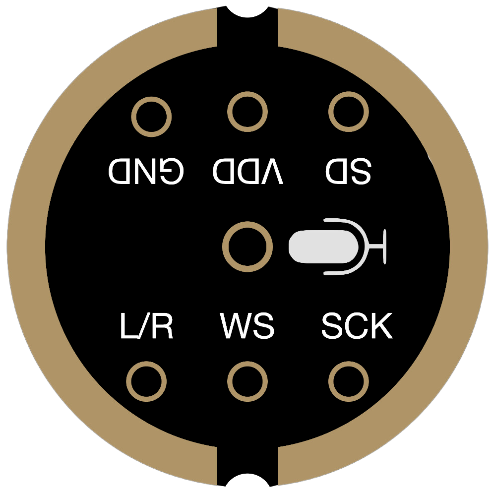
Pin Configuration and Descriptions
The INM441 microphone typically has two pins for electrical connections. Below is the pinout description:
| Pin | Name | Description |
|---|---|---|
| 1 | V+ (Power) | Positive supply voltage (1.5V to 10V) |
| 2 | GND | Ground connection for the microphone |
Note: Some variants of the INM441 may include a third pin for additional functionality, such as an output signal or biasing. Refer to the specific datasheet for details.
Usage Instructions
How to Use the INM441 in a Circuit
- Power Supply: Connect the V+ pin to a stable DC voltage source within the operating range (1.5V to 10V). A typical supply voltage is 3V.
- Ground Connection: Connect the GND pin to the ground of your circuit.
- Output Signal: The output signal is typically taken from the V+ pin through a coupling capacitor. This capacitor blocks DC components and allows the AC audio signal to pass through.
- Load Resistor: Use a pull-down resistor (typically 2.2 kΩ) between the V+ pin and GND to ensure proper biasing of the microphone.
Example Circuit
Below is a simple circuit diagram for connecting the INM441 microphone to an amplifier or microcontroller:
   V+ (Power) ---- R (2.2 kΩ) ---- +V (Supply Voltage)
                  |
                  C (Coupling Capacitor)
                  |
                Signal Output ----> Amplifier/Microcontroller
   GND ---------------------------- GND
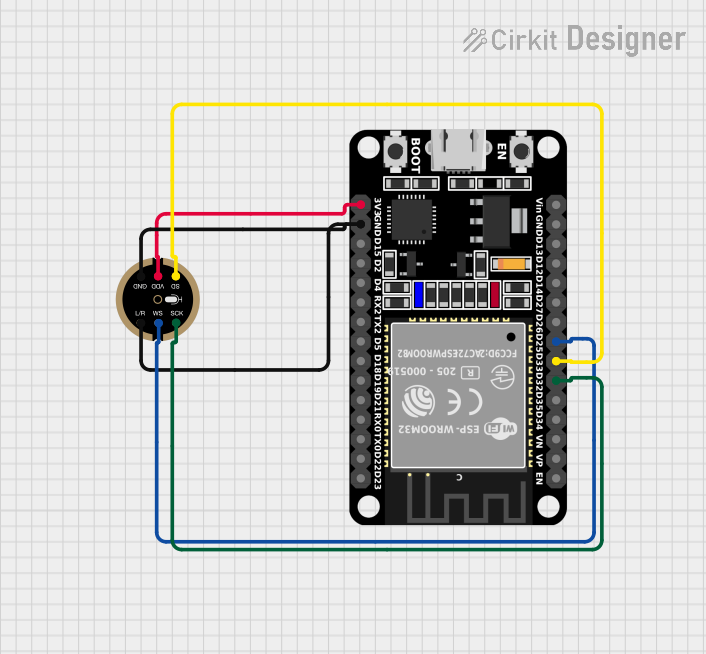
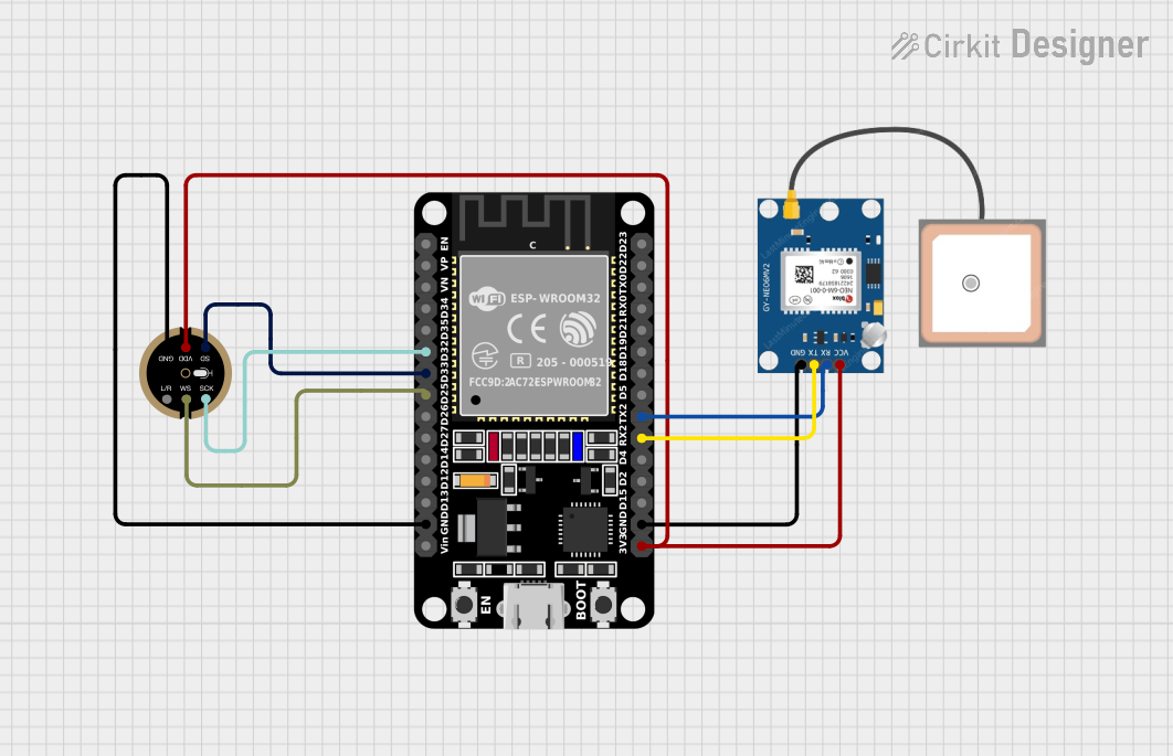
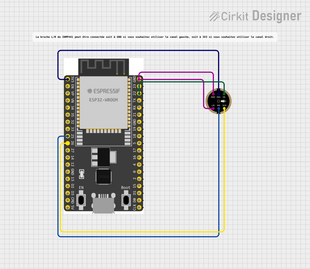
Using the INM441 with an Arduino UNO
The INM441 can be connected to an Arduino UNO for audio input. Below is an example of how to set up the circuit and code:
Circuit Connections
- Connect the V+ pin of the INM441 to the 3.3V pin on the Arduino.
- Connect the GND pin of the INM441 to the GND pin on the Arduino.
- Use a coupling capacitor (e.g., 10 µF) to connect the V+ pin to an analog input pin (e.g., A0) on the Arduino.
Arduino Code Example
// INM441 Microphone Example with Arduino UNO
// This code reads the analog signal from the microphone and prints the values
// to the Serial Monitor. Ensure the microphone is connected to analog pin A0.

const int micPin = A0; // Microphone connected to analog pin A0

void setup() {
  Serial.begin(9600); // Initialize serial communication at 9600 baud
}

void loop() {
  int micValue = analogRead(micPin); // Read the analog value from the microphone
  Serial.println(micValue); // Print the value to the Serial Monitor

  delay(10); // Small delay to stabilize readings
}
Note: The analog values from the microphone will vary based on the sound intensity. You can process these values further for applications like sound level detection or audio analysis.
Important Considerations and Best Practices
- Power Supply Stability: Ensure the power supply is stable and free from noise to avoid interference in the microphone's output.
- Coupling Capacitor: Use a high-quality coupling capacitor to prevent distortion in the audio signal.
- Placement: Place the microphone away from high-frequency noise sources (e.g., switching regulators) to maintain signal clarity.
- Amplification: The output signal from the INM441 is low and may require amplification for certain applications.
Troubleshooting and FAQs
Common Issues and Solutions
No Output Signal
- Cause: Incorrect wiring or missing pull-down resistor.
- Solution: Verify the connections and ensure a 2.2 kΩ resistor is connected between V+ and GND.
Distorted Audio
- Cause: Insufficient coupling capacitor value or noisy power supply.
- Solution: Use a larger coupling capacitor (e.g., 10 µF) and ensure the power supply is clean.
Low Sensitivity
- Cause: Microphone placement or insufficient amplification.
- Solution: Place the microphone closer to the sound source and use an appropriate amplifier.
High Noise in Output
- Cause: Electromagnetic interference or poor grounding.
- Solution: Shield the microphone and ensure proper grounding in the circuit.
FAQs
Q: Can the INM441 be used with a 5V power supply?
A: Yes, the INM441 operates within a voltage range of 1.5V to 10V, so a 5V supply is suitable.
Q: What is the purpose of the coupling capacitor?
A: The coupling capacitor blocks DC components from the microphone's output, allowing only the AC audio signal to pass through.
Q: Can the INM441 detect ultrasonic frequencies?
A: No, the INM441 is designed for audio frequencies with a range of 20 Hz to 20 kHz.
Q: Is the INM441 suitable for outdoor use?
A: The INM441 is not weatherproof. For outdoor use, additional protection (e.g., a waterproof housing) is required.
By following this documentation, you can effectively integrate the INM441 microphone into your projects and achieve high-quality audio performance.