Cirkit Designer Logo
Cirkit Designer
Your all-in-one circuit design IDE
Home / 
Component Documentation

How to Use Power supply buck 12v 5v 3.3V: Examples, Pinouts, and Specs

Image of Power supply buck 12v 5v 3.3V
Cirkit Designer LogoDesign with Power supply buck 12v 5v 3.3V in Cirkit Designer

Introduction

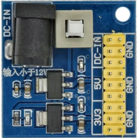
A buck power supply is a type of DC-DC converter that steps down voltage from a higher level (12V) to lower levels (5V and 3.3V) efficiently. It is widely used in electronic circuits to provide stable and regulated output voltages for powering microcontrollers, sensors, and other low-voltage devices. This component is highly efficient, compact, and ideal for applications where power conservation and heat management are critical.

Explore Projects Built with Power supply buck 12v 5v 3.3V

Use Cirkit Designer to design, explore, and prototype these projects online. Some projects support real-time simulation. Click "Open Project" to start designing instantly!
Multi-Stage Voltage Regulation and Indicator LED Circuit
Image of Subramanyak_Power_Circuit: A project utilizing Power supply buck 12v 5v 3.3V in a practical application
This circuit is designed for power management, featuring buck and boost converters for voltage adjustment, and linear regulators for stable voltage output. It includes LEDs for status indication, and terminal blocks for external connections.
Cirkit Designer LogoOpen Project in Cirkit Designer
USB Power Supply with Overcurrent Protection
Image of USB Charging port: A project utilizing Power supply buck 12v 5v 3.3V in a practical application
This circuit is designed to step down voltage from a 12V battery to a lower voltage suitable for USB devices. It includes a buck converter connected to the battery through a fuse and fuse holder for overcurrent protection. The output of the buck converter is connected to a USB female port, providing a regulated power supply for USB-powered devices.
Cirkit Designer LogoOpen Project in Cirkit Designer
12V to 5V Power Supply with LED Indicator and Push Switch
Image of Power Supply LVCO: A project utilizing Power supply buck 12v 5v 3.3V in a practical application
This circuit is a 12V to 5V regulated power supply with an LED indicator. It uses a 5408 diode for reverse polarity protection, an LM340T5 7805 voltage regulator to step down the voltage to 5V, and a push switch to control the LED indicator. The circuit also includes capacitors for filtering and a resistor to limit the current through the LED.
Cirkit Designer LogoOpen Project in Cirkit Designer
12V UPS System with Dual 18650 Li-ion Battery Backup and Voltage Regulation
Image of Power supply: A project utilizing Power supply buck 12v 5v 3.3V in a practical application
This circuit is designed to provide an uninterruptible power supply (UPS) system with a 12V DC output. It includes a 12V 5A power supply connected to an AC source through a toggle switch, which charges a pair of 18650 Li-ion batteries via a voltage regulator (XL4016). The UPS module ensures a continuous power supply to the load by switching between the power supply and the battery bank.
Cirkit Designer LogoOpen Project in Cirkit Designer

Explore Projects Built with Power supply buck 12v 5v 3.3V

Use Cirkit Designer to design, explore, and prototype these projects online. Some projects support real-time simulation. Click "Open Project" to start designing instantly!
Image of Subramanyak_Power_Circuit: A project utilizing Power supply buck 12v 5v 3.3V in a practical application
Multi-Stage Voltage Regulation and Indicator LED Circuit
This circuit is designed for power management, featuring buck and boost converters for voltage adjustment, and linear regulators for stable voltage output. It includes LEDs for status indication, and terminal blocks for external connections.
Cirkit Designer LogoOpen Project in Cirkit Designer
Image of USB Charging port: A project utilizing Power supply buck 12v 5v 3.3V in a practical application
USB Power Supply with Overcurrent Protection
This circuit is designed to step down voltage from a 12V battery to a lower voltage suitable for USB devices. It includes a buck converter connected to the battery through a fuse and fuse holder for overcurrent protection. The output of the buck converter is connected to a USB female port, providing a regulated power supply for USB-powered devices.
Cirkit Designer LogoOpen Project in Cirkit Designer
Image of Power Supply LVCO: A project utilizing Power supply buck 12v 5v 3.3V in a practical application
12V to 5V Power Supply with LED Indicator and Push Switch
This circuit is a 12V to 5V regulated power supply with an LED indicator. It uses a 5408 diode for reverse polarity protection, an LM340T5 7805 voltage regulator to step down the voltage to 5V, and a push switch to control the LED indicator. The circuit also includes capacitors for filtering and a resistor to limit the current through the LED.
Cirkit Designer LogoOpen Project in Cirkit Designer
Image of Power supply: A project utilizing Power supply buck 12v 5v 3.3V in a practical application
12V UPS System with Dual 18650 Li-ion Battery Backup and Voltage Regulation
This circuit is designed to provide an uninterruptible power supply (UPS) system with a 12V DC output. It includes a 12V 5A power supply connected to an AC source through a toggle switch, which charges a pair of 18650 Li-ion batteries via a voltage regulator (XL4016). The UPS module ensures a continuous power supply to the load by switching between the power supply and the battery bank.
Cirkit Designer LogoOpen Project in Cirkit Designer

Common Applications and Use Cases

  • Powering microcontrollers (e.g., Arduino, Raspberry Pi)
  • Supplying voltage to sensors, modules, and communication devices
  • Battery-powered systems to step down voltage for low-power components
  • Robotics and IoT devices requiring multiple voltage levels
  • General-purpose voltage regulation in embedded systems

Technical Specifications

Key Technical Details

Parameter Value
Input Voltage Range 6V to 24V
Output Voltage Options 12V, 5V, 3.3V
Maximum Output Current 3A (varies by output voltage)
Efficiency Up to 95%
Switching Frequency 150 kHz
Operating Temperature -40°C to +85°C
Dimensions Typically 25mm x 20mm x 10mm

Pin Configuration and Descriptions

Pin Name Description
VIN Input voltage pin (connect 6V-24V DC)
GND Ground pin (common ground for input and output)
VOUT 12V 12V output pin
VOUT 5V 5V output pin
VOUT 3.3V 3.3V output pin

Usage Instructions

How to Use the Component in a Circuit

  1. Connect the Input Voltage:
    • Connect the VIN pin to a DC power source (6V to 24V).
    • Ensure the input voltage is within the specified range to avoid damage.
  2. Connect the Ground:
    • Connect the GND pin to the ground of your circuit.
  3. Select the Desired Output Voltage:
    • Use the VOUT 12V, VOUT 5V, or VOUT 3.3V pin to power your device.
    • Ensure the connected load does not exceed the maximum output current (3A).
  4. Add Decoupling Capacitors (Optional):
    • For improved stability, place a 10µF capacitor near the output pins.
  5. Power On:
    • Turn on the input power supply and verify the output voltage using a multimeter.

Important Considerations and Best Practices

  • Heat Dissipation: If the load current is high, ensure proper ventilation or attach a heatsink to prevent overheating.
  • Input Voltage Range: Always check the input voltage to ensure it is within the specified range.
  • Load Regulation: Avoid sudden changes in load current to maintain stable output voltage.
  • Short Circuit Protection: Some modules include built-in protection, but verify this feature before use.

Example: Connecting to an Arduino UNO

To power an Arduino UNO using the 5V output of the buck converter:

  1. Connect the VIN pin of the buck converter to a 12V DC power source.
  2. Connect the GND pin of the buck converter to the GND of the Arduino.
  3. Connect the VOUT 5V pin of the buck converter to the 5V pin of the Arduino.

Sample Code for Testing

// This code blinks an LED connected to pin 13 of the Arduino UNO.
// Ensure the Arduino is powered via the 5V output of the buck converter.

void setup() {
  pinMode(13, OUTPUT); // Set pin 13 as an output
}

void loop() {
  digitalWrite(13, HIGH); // Turn the LED on
  delay(1000);            // Wait for 1 second
  digitalWrite(13, LOW);  // Turn the LED off
  delay(1000);            // Wait for 1 second
}

Troubleshooting and FAQs

Common Issues and Solutions

  1. No Output Voltage:
    • Cause: Input voltage is too low or disconnected.
    • Solution: Verify the input voltage is within the 6V-24V range and securely connected.
  2. Overheating:
    • Cause: Excessive load current or poor ventilation.
    • Solution: Reduce the load current or add a heatsink for better heat dissipation.
  3. Output Voltage Fluctuations:
    • Cause: Insufficient decoupling or unstable input voltage.
    • Solution: Add a 10µF capacitor near the output pins and ensure a stable input voltage.
  4. Short Circuit Protection Triggered:
    • Cause: Output pins are shorted.
    • Solution: Disconnect the power, check for shorts, and reconnect after resolving the issue.

FAQs

Q: Can I use this module to power multiple devices simultaneously?
A: Yes, as long as the total current draw does not exceed the maximum output current (3A).

Q: Is the output voltage adjustable?
A: No, this module provides fixed output voltages of 12V, 5V, and 3.3V.

Q: Can I use this module with a battery as the input source?
A: Yes, ensure the battery voltage is within the 6V-24V range.

Q: Does this module have reverse polarity protection?
A: Most modules do not include reverse polarity protection. Always double-check the polarity before connecting the input voltage.