How to Use USB-C Terminal Female GND+5V: Examples, Pinouts, and Specs
Introduction
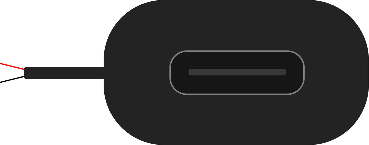
The USB-C Terminal Female GND+5V is a compact and versatile connector designed to provide a simple interface for accessing the power lines of a USB-C connection. This component is commonly used in DIY electronics projects, prototyping, and power delivery applications. It allows users to easily tap into the +5V and GND pins of a USB-C cable without requiring complex soldering or additional circuitry.
Explore Projects Built with USB-C Terminal Female GND+5V


Explore Projects Built with USB-C Terminal Female GND+5V
Common Applications and Use Cases
- Powering low-power electronic devices and modules
- Prototyping USB-C power delivery circuits
- Educational projects for understanding USB-C power lines
- Creating custom USB-C power adapters or chargers
Technical Specifications
The USB-C Terminal Female GND+5V is designed to provide access to the basic power pins of a USB-C connection. Below are the key technical details:
| Parameter | Value |
|---|---|
| Connector Type | USB-C Female Terminal Block |
| Voltage Output | +5V DC |
| Current Rating | Up to 3A |
| Pin Configuration | GND, +5V |
| Operating Temperature | -20°C to 85°C |
| Dimensions | Varies by manufacturer |
Pin Configuration and Descriptions
The USB-C Terminal Female GND+5V typically has two screw terminals for easy wire connections. Below is the pin configuration:
| Pin | Label | Description |
|---|---|---|
| 1 | GND | Ground connection for the circuit |
| 2 | +5V | +5V DC power output from the USB-C port |
Usage Instructions
How to Use the Component in a Circuit
- Connect the USB-C Cable: Plug a USB-C cable into the female terminal block. Ensure the cable is connected to a power source capable of providing +5V.
- Wire the Terminals: Use the screw terminals to connect wires to the GND and +5V outputs. Tighten the screws securely to ensure a stable connection.
- Power Your Circuit: Connect the GND and +5V wires to your circuit or device. Verify that the connected device operates within the voltage and current limits of the USB-C power source.
Important Considerations and Best Practices
- Check Power Source Compatibility: Ensure the USB-C power source provides a stable +5V output. Some USB-C power adapters may require a device handshake to enable power delivery.
- Avoid Overloading: Do not exceed the current rating of the USB-C power source or the terminal block (typically 3A).
- Secure Connections: Ensure all wires are securely fastened to the screw terminals to prevent accidental disconnections.
- Polarity Awareness: Double-check the polarity of the connections (GND and +5V) to avoid damaging your circuit.
Example: Using with an Arduino UNO
The USB-C Terminal Female GND+5V can be used to power an Arduino UNO. Below is an example setup:
- Connect the +5V terminal to the Arduino's 5V pin.
- Connect the GND terminal to the Arduino's GND pin.
- Plug the USB-C cable into a 5V power source.
Here is a simple Arduino sketch to blink an LED while powered by the USB-C terminal:
// Simple LED Blink Example
// This code blinks an LED connected to pin 13 of the Arduino UNO.
// Ensure the Arduino is powered via the USB-C Terminal Female GND+5V.

void setup() {
  pinMode(13, OUTPUT); // Set pin 13 as an output
}

void loop() {
  digitalWrite(13, HIGH); // Turn the LED on
  delay(1000);            // Wait for 1 second
  digitalWrite(13, LOW);  // Turn the LED off
  delay(1000);            // Wait for 1 second
}
Troubleshooting and FAQs
Common Issues Users Might Face
No Power Output:
- Cause: The USB-C power source may not be providing power.
- Solution: Verify that the USB-C cable is connected to a functional power source. Some USB-C adapters require a device handshake to enable power delivery.
Loose Connections:
- Cause: Wires may not be securely fastened to the screw terminals.
- Solution: Tighten the screws on the terminal block to ensure a stable connection.
Overheating:
- Cause: Excessive current draw beyond the rated limit.
- Solution: Ensure the connected device does not exceed the 3A current rating.
Incorrect Polarity:
- Cause: Wires connected to the wrong terminals.
- Solution: Double-check the polarity of the connections (GND and +5V) before powering the circuit.
FAQs
Q: Can this component be used for data transfer?
A: No, the USB-C Terminal Female GND+5V is designed only for accessing the power lines (+5V and GND). It does not support data transfer.
Q: What happens if I connect a device that requires more than 3A?
A: Exceeding the current rating may cause overheating or damage to the terminal block and USB-C power source. Always ensure your device operates within the specified limits.
Q: Can I use this with a USB-C PD (Power Delivery) charger?
A: Yes, but only if the charger defaults to +5V output or if a compatible device is used to negotiate the desired voltage.