
How to Use 2.5mm Audio Jack: Examples, Pinouts, and Specs
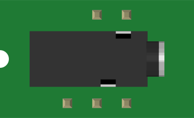
 Design with 2.5mm Audio Jack in Cirkit Designer
Introduction
The 2.5mm Audio Jack (Manufacturer: SparkFun Electronics, Part ID: PRT-08032) is a compact connector designed for audio signal transmission. It is commonly used in devices such as headphones, microphones, and other audio equipment. This jack allows for the seamless transfer of audio signals between devices, making it an essential component in audio-related projects.
Explore Projects Built with 2.5mm Audio Jack
 Open Project in Cirkit Designer
 Open Project in Cirkit Designer
 Open Project in Cirkit Designer
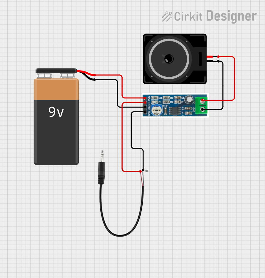 Open Project in Cirkit Designer
Explore Projects Built with 2.5mm Audio Jack
Open Project in Cirkit DesignerOpen Project in Cirkit DesignerOpen Project in Cirkit DesignerOpen Project in Cirkit DesignerCommon Applications and Use Cases
- Headphone and microphone connections
- Audio input/output for portable devices
- DIY audio projects and prototyping
- Integration into audio amplifiers and mixers
- Use in embedded systems for audio signal processing
Technical Specifications
The following table outlines the key technical details of the 2.5mm Audio Jack:
| Parameter | Specification |
|---|---|
| Manufacturer | SparkFun Electronics |
| Part ID | PRT-08032 |
| Connector Type | 2.5mm Stereo Audio Jack |
| Number of Contacts | 3 (Tip, Ring, Sleeve - TRS) |
| Mounting Style | Through-Hole |
| Housing Material | Plastic |
| Contact Material | Metal (Gold or Nickel Plated) |
| Maximum Voltage Rating | 12V |
| Maximum Current Rating | 1A |
| Operating Temperature | -25°C to +85°C |
Pin Configuration and Descriptions
The 2.5mm Audio Jack has three primary connections, as detailed below:
| Pin Name | Description |
|---|---|
| Tip (T) | Carries the left audio channel signal |
| Ring (R) | Carries the right audio channel signal |
| Sleeve (S) | Serves as the ground connection |
Usage Instructions
How to Use the Component in a Circuit
- Identify the Pins: Locate the Tip, Ring, and Sleeve connections on the audio jack.
- Soldering: Secure the audio jack onto a PCB using the through-hole mounting points. Ensure proper soldering to avoid loose connections.
- Connect to Circuit:
- Connect the Tip pin to the left audio channel signal source.
- Connect the Ring pin to the right audio channel signal source.
- Connect the Sleeve pin to the ground of the circuit.
- Test the Connections: Use a multimeter to verify continuity and ensure proper connections.
Important Considerations and Best Practices
- Signal Integrity: Use shielded cables to minimize noise and interference in audio signals.
- Voltage and Current Ratings: Do not exceed the maximum voltage (12V) or current (1A) ratings to prevent damage.
- Mounting: Ensure the jack is securely mounted to avoid mechanical stress on the solder joints.
- Compatibility: Verify that the connected device uses a 2.5mm TRS connector. This jack is not compatible with 3.5mm connectors without an adapter.
Example: Connecting to an Arduino UNO
The 2.5mm Audio Jack can be used to interface audio signals with an Arduino UNO for audio processing. Below is an example of how to read an audio signal from the jack's Tip pin using the Arduino's analog input.
// Example: Reading audio signal from a 2.5mm Audio Jack
// Connect the Tip pin to Arduino A0, Sleeve to GND, and leave Ring unconnected
// This code reads the audio signal and prints the analog value to the Serial Monitor

const int audioPin = A0; // Pin connected to the Tip (left audio channel)

void setup() {
  Serial.begin(9600); // Initialize serial communication at 9600 baud
}

void loop() {
  int audioSignal = analogRead(audioPin); // Read the analog signal from the jack
  Serial.println(audioSignal); // Print the signal value to the Serial Monitor
  delay(10); // Small delay to stabilize readings
}
Note: The audio signal must be within the Arduino's input voltage range (0-5V). Use a voltage divider or capacitor coupling if necessary to condition the signal.
Troubleshooting and FAQs
Common Issues and Solutions
No Audio Signal Detected:
- Cause: Incorrect wiring or loose connections.
- Solution: Verify the connections to the Tip, Ring, and Sleeve pins. Ensure proper soldering.
Excessive Noise or Interference:
- Cause: Unshielded cables or poor grounding.
- Solution: Use shielded cables and ensure the Sleeve pin is properly connected to ground.
Audio Jack Not Fitting:
- Cause: Using a 3.5mm connector instead of a 2.5mm connector.
- Solution: Use a 2.5mm TRS connector or an appropriate adapter.
Overheating During Soldering:
- Cause: Prolonged exposure to high soldering temperatures.
- Solution: Use a temperature-controlled soldering iron and limit soldering time to a few seconds per pin.
FAQs
Q1: Can this jack be used for mono audio signals?
A1: Yes, the jack can be used for mono signals by connecting the Tip and Ring pins together to carry the same signal.
Q2: Is this jack compatible with 3.5mm connectors?
A2: No, this jack is specifically designed for 2.5mm connectors. Use an adapter for compatibility with 3.5mm connectors.
Q3: Can this jack handle digital audio signals?
A3: While it is primarily designed for analog audio signals, it can handle digital signals within its voltage and current ratings.
Q4: What is the difference between TRS and TRRS connectors?
A4: TRS connectors have three contacts (Tip, Ring, Sleeve), while TRRS connectors have four (Tip, Ring, Ring, Sleeve) and are used for additional functionality, such as microphone input.
This concludes the documentation for the SparkFun Electronics 2.5mm Audio Jack (PRT-08032).