How to Use Cytron MDD10A - 10Amp 5V-30V DC Motor Driver (2 Channels): Examples, Pinouts, and Specs
Introduction
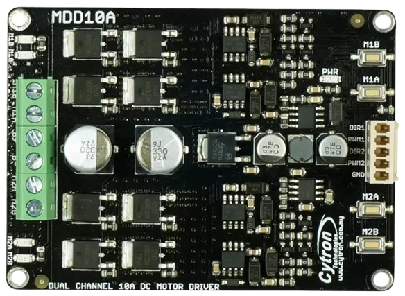
The Cytron MDD10A is a robust dual-channel DC motor driver designed to control two DC motors with a maximum continuous current of 10A per channel. It supports a wide operating voltage range of 5V to 30V, making it ideal for a variety of robotics and automation applications. The MDD10A is equipped with multiple control modes, including PWM, and features built-in protection mechanisms for safe and reliable operation.
Explore Projects Built with Cytron MDD10A - 10Amp 5V-30V DC Motor Driver (2 Channels)


Explore Projects Built with Cytron MDD10A - 10Amp 5V-30V DC Motor Driver (2 Channels)
Common Applications
- Robotics (e.g., mobile robots, robotic arms)
- Automated guided vehicles (AGVs)
- Conveyor belt systems
- DIY motorized projects
- Industrial automation systems
Technical Specifications
The following table outlines the key technical specifications of the Cytron MDD10A:
| Parameter | Specification |
|---|---|
| Operating Voltage | 5V to 30V DC |
| Continuous Current | 10A per channel |
| Peak Current | 30A per channel (for 10 seconds) |
| Control Modes | PWM, Direction, and Brake |
| PWM Frequency | Up to 20 kHz |
| Logic Voltage | 3.3V or 5V compatible |
| Protection Features | Overcurrent, Overtemperature, Reverse Polarity |
| Dimensions | 84mm x 62mm x 25mm |
| Weight | 80g |
Pin Configuration and Descriptions
The MDD10A has a total of 12 pins for motor control and power connections. The table below describes each pin:
| Pin Name | Type | Description |
|---|---|---|
| VM | Power Input | Motor power supply (5V to 30V DC). Connect to the positive terminal of the battery. |
| GND | Power Input | Ground connection. Connect to the negative terminal of the battery. |
| M1A | Motor Output | Output terminal A for Motor 1. |
| M1B | Motor Output | Output terminal B for Motor 1. |
| M2A | Motor Output | Output terminal A for Motor 2. |
| M2B | Motor Output | Output terminal B for Motor 2. |
| DIR1 | Control Input | Direction control for Motor 1. High = Forward, Low = Reverse. |
| PWM1 | Control Input | PWM signal for Motor 1 speed control. |
| DIR2 | Control Input | Direction control for Motor 2. High = Forward, Low = Reverse. |
| PWM2 | Control Input | PWM signal for Motor 2 speed control. |
| EN | Control Input | Enable pin. High = Enable motor driver, Low = Disable motor driver. |
| 5V | Power Output | 5V output for external logic circuits (max 100mA). |
Usage Instructions
How to Use the MDD10A in a Circuit
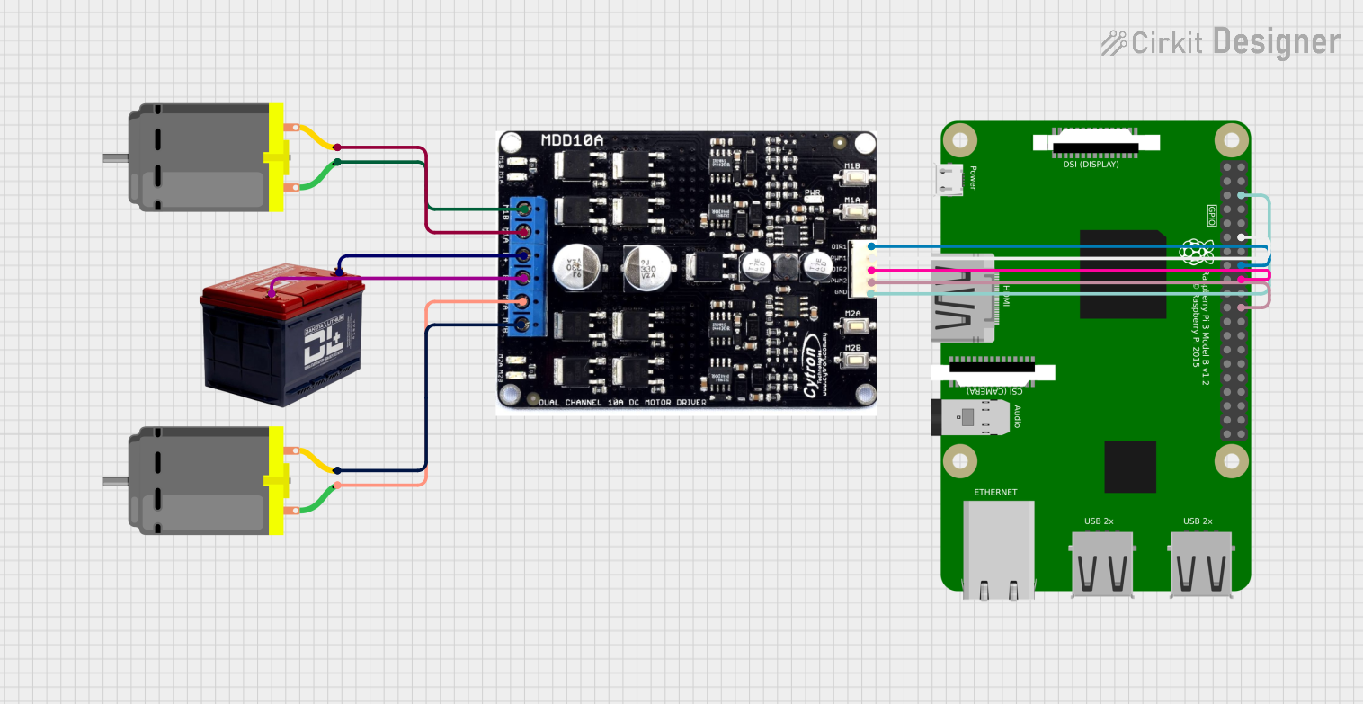
Power Connections:
- Connect the motor power supply (5V to 30V DC) to the
VMpin. - Connect the ground of the power supply to the
GNDpin.
- Connect the motor power supply (5V to 30V DC) to the
Motor Connections:
- Connect the terminals of Motor 1 to
M1AandM1B. - Connect the terminals of Motor 2 to
M2AandM2B.
- Connect the terminals of Motor 1 to
Control Connections:
- Use the
DIR1andPWM1pins to control the direction and speed of Motor 1. - Use the
DIR2andPWM2pins to control the direction and speed of Motor 2. - Optionally, connect the
ENpin to enable or disable the motor driver.
- Use the
Logic Voltage Compatibility:
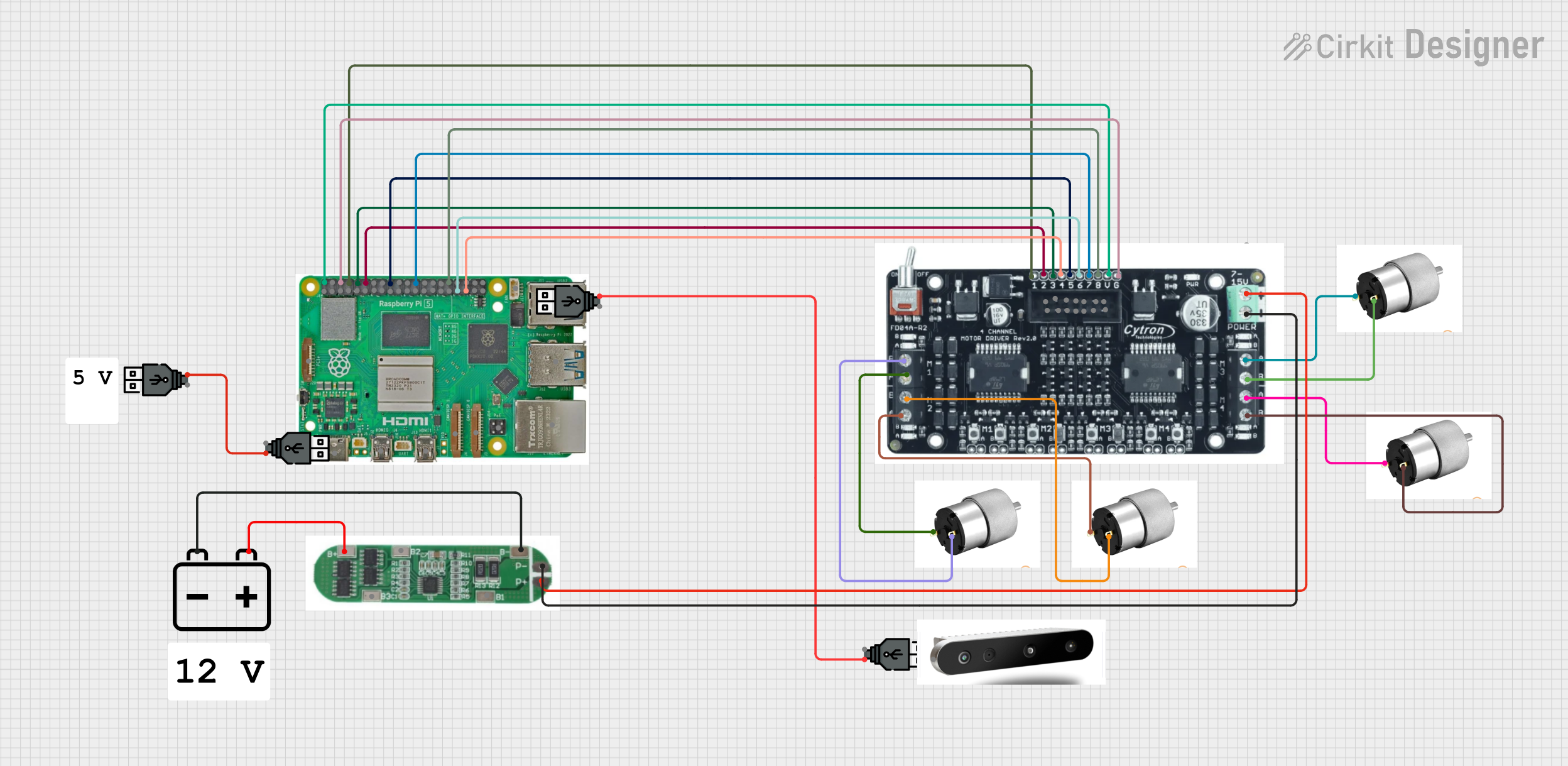
- The control pins are compatible with both 3.3V and 5V logic levels, making it easy to interface with microcontrollers like Arduino or Raspberry Pi.
Important Considerations and Best Practices
- Ensure the motor power supply voltage is within the specified range (5V to 30V).
- Use appropriate heat dissipation methods (e.g., heatsinks) if operating at high currents for extended periods.
- Avoid reversing the polarity of the power supply to prevent damage to the driver.
- Use a fuse or circuit breaker to protect the motor driver and connected components.
Example: Connecting to an Arduino UNO
Below is an example of how to control two DC motors using the MDD10A and an Arduino UNO:
Circuit Connections
- Connect
DIR1to Arduino pin 7 andPWM1to Arduino pin 6. - Connect
DIR2to Arduino pin 4 andPWM2to Arduino pin 5. - Connect the
ENpin to Arduino pin 8. - Connect the motor power supply to
VMandGND.
Arduino Code
// Define motor control pins
#define DIR1 7  // Direction control for Motor 1
#define PWM1 6  // PWM control for Motor 1
#define DIR2 4  // Direction control for Motor 2
#define PWM2 5  // PWM control for Motor 2
#define EN 8    // Enable pin for motor driver

void setup() {
  // Set motor control pins as outputs
  pinMode(DIR1, OUTPUT);
  pinMode(PWM1, OUTPUT);
  pinMode(DIR2, OUTPUT);
  pinMode(PWM2, OUTPUT);
  pinMode(EN, OUTPUT);

  // Enable the motor driver
  digitalWrite(EN, HIGH);
}

void loop() {
  // Motor 1: Forward at 50% speed
  digitalWrite(DIR1, HIGH);
  analogWrite(PWM1, 128); // 50% duty cycle (128 out of 255)

  // Motor 2: Reverse at 75% speed
  digitalWrite(DIR2, LOW);
  analogWrite(PWM2, 192); // 75% duty cycle (192 out of 255)

  delay(2000); // Run motors for 2 seconds

  // Stop both motors
  analogWrite(PWM1, 0);
  analogWrite(PWM2, 0);

  delay(2000); // Wait for 2 seconds before repeating
}
Troubleshooting and FAQs
Common Issues and Solutions
Motors Not Running:
- Ensure the
ENpin is set to HIGH to enable the motor driver. - Verify that the power supply voltage is within the specified range (5V to 30V).
- Check the connections to the motors and control pins.
- Ensure the
Overheating:
- Reduce the motor load or operating current.
- Use a heatsink or active cooling to dissipate heat.
Erratic Motor Behavior:
- Ensure the PWM signal frequency is within the supported range (up to 20 kHz).
- Check for loose or faulty connections.
Driver Not Responding to Control Signals:
- Verify that the control signals are compatible with the logic voltage (3.3V or 5V).
- Check the Arduino code for errors or incorrect pin assignments.
FAQs
Can the MDD10A drive stepper motors? No, the MDD10A is designed for DC motors only. For stepper motors, use a dedicated stepper motor driver.
What happens if the current exceeds 10A? The driver includes overcurrent protection, which will shut down the output to prevent damage.
Can I use the MDD10A with a Raspberry Pi? Yes, the control pins are compatible with the 3.3V logic level of the Raspberry Pi.
Is reverse polarity protection included? Yes, the MDD10A has built-in reverse polarity protection for the power supply.