
How to Use SparkFun FTDI Basic Breakout (3.3V): Examples, Pinouts, and Specs
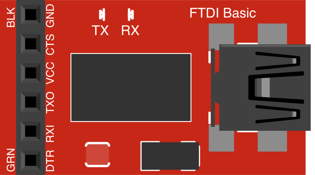
 Design with SparkFun FTDI Basic Breakout (3.3V) in Cirkit Designer
Introduction
The SparkFun FTDI Basic Breakout (3.3V) (Manufacturer Part ID: DEV-09873) is a compact USB-to-serial converter designed to facilitate seamless communication between a computer and microcontrollers or other serial devices. Operating at a voltage of 3.3V, this breakout board is ideal for programming and debugging microcontrollers, such as Arduino-compatible boards, or for interfacing with other devices that use UART communication.
Explore Projects Built with SparkFun FTDI Basic Breakout (3.3V)
 Open Project in Cirkit Designer
 Open Project in Cirkit Designer
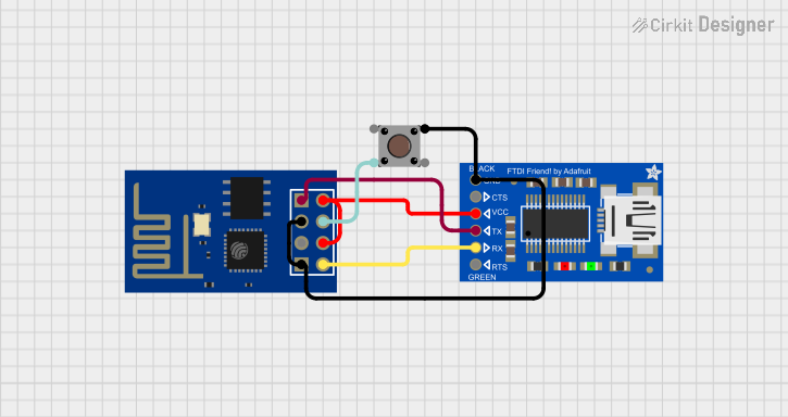 Open Project in Cirkit Designer
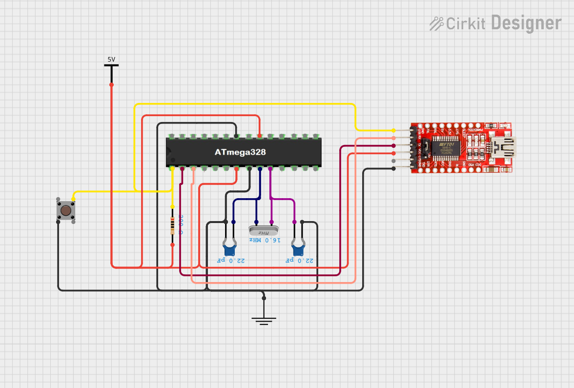 Open Project in Cirkit Designer
Explore Projects Built with SparkFun FTDI Basic Breakout (3.3V)
Open Project in Cirkit DesignerOpen Project in Cirkit DesignerOpen Project in Cirkit DesignerOpen Project in Cirkit DesignerCommon Applications and Use Cases
- Programming Arduino Pro, Pro Mini, and other microcontrollers.
- Debugging and testing serial communication in embedded systems.
- Interfacing with sensors, modules, or devices that use UART communication.
- USB-to-serial communication for custom projects.
Technical Specifications
The SparkFun FTDI Basic Breakout (3.3V) is built around the FT232RL chip from FTDI, which provides reliable USB-to-serial conversion. Below are the key technical details:
Key Technical Details
- Operating Voltage: 3.3V
- USB Interface: Mini-B USB connector
- Chipset: FTDI FT232RL
- Communication Protocol: UART (TX, RX)
- Baud Rate: Configurable up to 3 Mbps
- Power Output: 3.3V (50mA max)
- LED Indicators: Power (Red), TX (Green), RX (Yellow)
- Dimensions: 1.3" x 0.6" (33mm x 15mm)
Pin Configuration and Descriptions
The breakout board has a 6-pin header that connects to your target device. Below is the pinout:
| Pin | Name | Description |
|---|---|---|
| 1 | DTR | Data Terminal Ready. Used for resetting microcontrollers during programming. |
| 2 | RXI | Receive Data. Data received from the target device to the computer. |
| 3 | TXO | Transmit Data. Data sent from the computer to the target device. |
| 4 | VCC | 3.3V power output. Can power the target device (max 50mA). |
| 5 | CTS | Clear to Send. Used for hardware flow control (optional). |
| 6 | GND | Ground. Common ground connection between the breakout board and the target. |
Usage Instructions
How to Use the Component in a Circuit
Connect the FTDI Basic Breakout to Your Computer:
- Use a Mini-B USB cable to connect the breakout board to your computer. Ensure the drivers for the FT232RL chip are installed (available on the SparkFun website or FTDI's official site).
Connect to the Target Device:
- Align the 6-pin header of the breakout board with the corresponding pins on your target device (e.g., Arduino Pro Mini). Ensure the pin labels match (e.g., GND to GND, TXO to RX, RXI to TX).
Power the Target Device:
- If your target device operates at 3.3V and requires less than 50mA, you can power it directly from the breakout board's VCC pin. Otherwise, use an external power source.
Program or Communicate:
- Use a serial terminal program (e.g., Arduino IDE Serial Monitor, PuTTY) or upload code to your microcontroller via the breakout board.
Important Considerations and Best Practices
- Voltage Compatibility: Ensure your target device operates at 3.3V. Connecting a 5V device may damage the breakout board or the target.
- Driver Installation: Install the FTDI drivers before using the breakout board. Without the drivers, your computer may not recognize the device.
- Pin Alignment: Double-check the pin alignment between the breakout board and the target device to avoid incorrect connections.
- DTR Pin: The DTR pin is used to reset the microcontroller during programming. Ensure this pin is connected if programming an Arduino-compatible board.
Example: Using with Arduino UNO
Although the FTDI Basic Breakout is typically used with boards like the Arduino Pro Mini, it can also be used for serial communication with an Arduino UNO. Below is an example Arduino sketch and serial communication code:
Arduino Sketch
// Example sketch for testing serial communication with FTDI Basic Breakout
void setup() {
  Serial.begin(9600); // Initialize serial communication at 9600 baud
  Serial.println("FTDI Basic Breakout Test"); // Send a test message
}

void loop() {
  if (Serial.available() > 0) { // Check if data is received
    char received = Serial.read(); // Read the received character
    Serial.print("You sent: ");
    Serial.println(received); // Echo the received character back
  }
}
Serial Communication
- Upload the above sketch to your Arduino UNO.
- Connect the FTDI Basic Breakout to the Arduino UNO's RX and TX pins (cross-connect: TXO to RX, RXI to TX).
- Open the Serial Monitor in the Arduino IDE, set the baud rate to 9600, and test communication.
Troubleshooting and FAQs
Common Issues and Solutions
Computer Does Not Recognize the Breakout Board:
- Ensure the FTDI drivers are installed. Download and install the drivers from the SparkFun or FTDI website.
- Try a different USB cable or port. Some cables are power-only and do not support data transfer.
No Communication Between the Computer and Target Device:
- Verify the TX and RX connections. Ensure TXO on the breakout board connects to RX on the target device, and RXI connects to TX.
- Check the baud rate in your serial terminal program. It must match the baud rate set in your code.
Target Device Does Not Power On:
- Ensure the target device operates at 3.3V and does not draw more than 50mA. If it requires more current, use an external power source.
LED Indicators Not Working:
- The Power LED should light up when the breakout board is connected to a USB port. If it does not, check the USB connection and cable.
FAQs
Q: Can I use this breakout board with 5V devices?
A: No, the SparkFun FTDI Basic Breakout (3.3V) is designed for 3.3V devices. Using it with 5V devices may damage the board or the connected device. Use the 5V version of the breakout board for 5V devices.
Q: How do I reset my microcontroller using the DTR pin?
A: The DTR pin is automatically toggled during programming to reset the microcontroller. Ensure the DTR pin is connected to the reset pin of your microcontroller.
Q: Can I use this breakout board for general-purpose USB-to-serial communication?
A: Yes, the FTDI Basic Breakout can be used for any UART-based communication, provided the voltage levels are compatible.
Q: What is the maximum cable length I can use?
A: USB cables should generally not exceed 5 meters to ensure reliable communication. For longer distances, consider using USB extenders or repeaters.