Cirkit Designer LogoCirkit DesignerYour all-in-one circuit design IDE Launch Cirkit Designer App

How to Use Type-C USB 2-3S BMS 15W: Examples, Pinouts, and Specs

Image of Type-C USB 2-3S BMS 15WDesign with Type-C USB 2-3S BMS 15W in Cirkit Designer

Introduction

The Type-C USB 2-3S BMS 15W is a compact and efficient Battery Management System (BMS) designed for managing 2-3 cell lithium battery packs. It features a Type-C USB interface for charging and data transfer, making it highly versatile and user-friendly. This component ensures safe and reliable operation of lithium battery packs by providing overcharge, over-discharge, and short-circuit protection.

Explore Projects Built with Type-C USB 2-3S BMS 15W

Use Cirkit Designer to design, explore, and prototype these projects online. Some projects support real-time simulation. Click "Open Project" to start designing instantly!
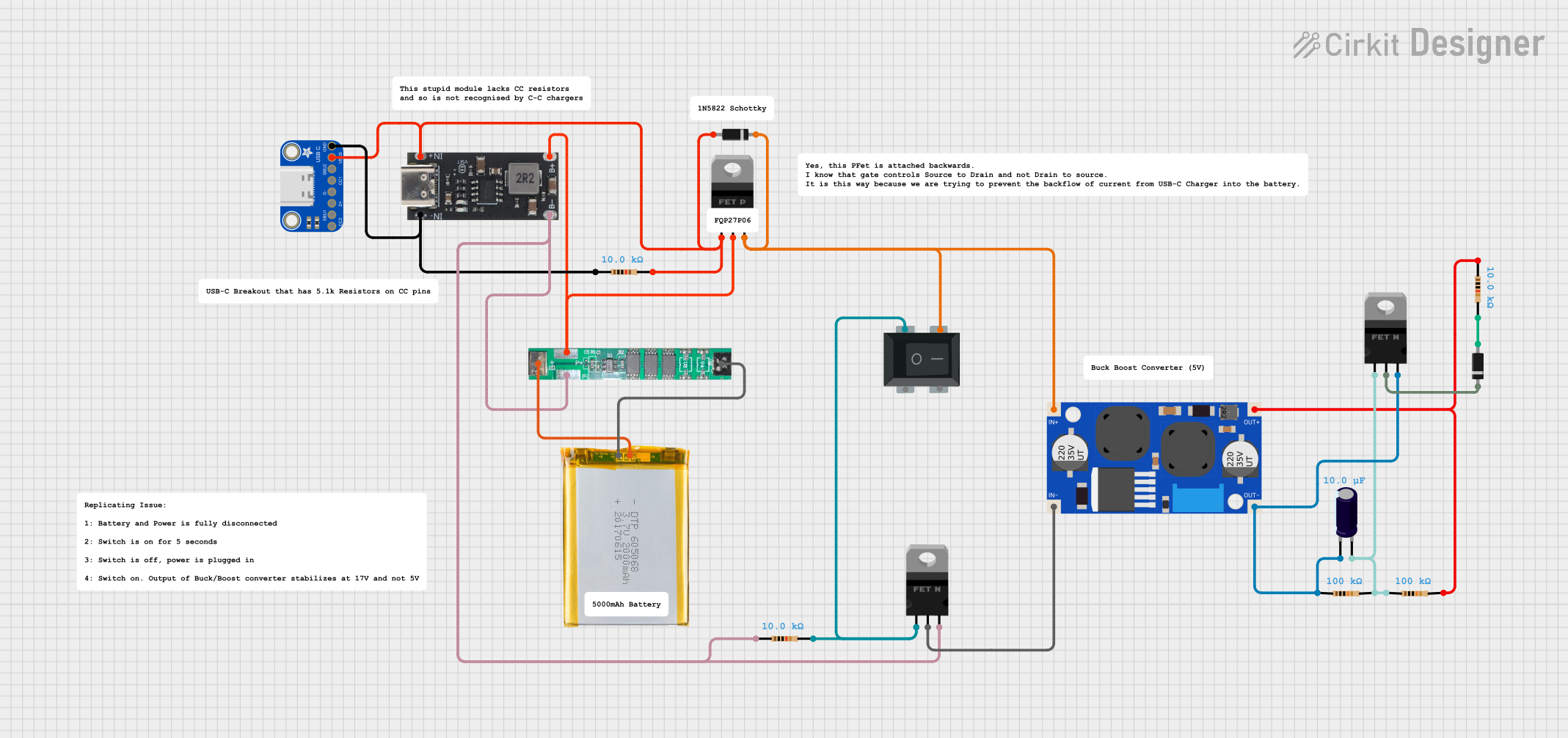
Image of Battery-Powered Boost Converter with USB Type-C and BMS: A project utilizing Type-C USB 2-3S BMS 15W in a practical application

Battery-Powered Boost Converter with USB Type-C and BMS

This circuit is a power management and conversion system that includes a boost converter, battery management system (BMS), and various MOSFETs and passive components. It is designed to regulate and boost the voltage from a 2000mAh battery, providing stable power output through a USB Type C interface. The circuit also includes protection and switching mechanisms to ensure safe and efficient power delivery.

Open Project in Cirkit Designer
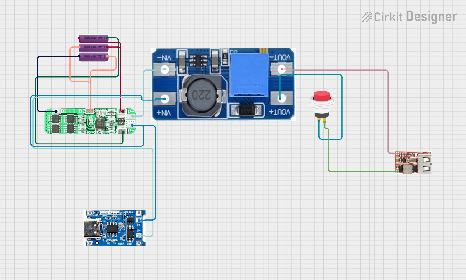
Image of Battery-Powered 18650 Li-ion Charger with USB Output and Adjustable Voltage Regulator: A project utilizing Type-C USB 2-3S BMS 15W in a practical application
Battery-Powered 18650 Li-ion Charger with USB Output and Adjustable Voltage Regulator

This circuit is a battery management and power supply system that uses three 3.7V batteries connected to a 3S 10A Li-ion 18650 Charger Protection Board Module for balanced charging and protection. The system includes a TP4056 Battery Charging Protection Module for additional charging safety, a Step Up Boost Power Converter to regulate and boost the voltage, and a USB regulator to provide a stable 5V output, controlled by a push switch.

Open Project in Cirkit Designer

Common Applications and Use Cases

Technical Specifications

Key Technical Details

Pin Configuration and Descriptions

The Type-C USB 2-3S BMS 15W has the following key connections:

Pin/Port Description
Type-C USB Port Input for charging the battery pack and data transfer.
B+ Positive terminal of the battery pack.
B- Negative terminal of the battery pack.
BM Middle connection point for balancing 2S or 3S battery packs.
P+ Positive output terminal for the load.
P- Negative output terminal for the load.
LED Indicators Status LEDs for charging, fully charged, and fault conditions.

Usage Instructions

How to Use the Component in a Circuit

  1. Connect the Battery Pack:
    • For a 2S battery pack, connect the positive terminal to B+, the negative terminal to B-, and the middle connection to BM.
    • For a 3S battery pack, connect the positive terminal to B+, the negative terminal to B-, and the intermediate connections to BM as required.
  2. Connect the Load:
    • Attach the load (e.g., a motor or circuit) to the P+ and P- terminals.
  3. Charging:
    • Use a Type-C USB cable to connect the BMS to a 5V power source for charging.
    • The LED indicators will show the charging status.
  4. Ensure Proper Ventilation:
    • Place the BMS in a well-ventilated area to prevent overheating during operation.

Important Considerations and Best Practices

Arduino UNO Example Code

If you are using the BMS to power an Arduino UNO, you can monitor the battery voltage using the following code:

// Arduino code to monitor battery voltage using an analog pin
const int batteryPin = A0; // Connect the battery's positive terminal to A0 via a voltage divider
float voltage = 0.0;

void setup() {
  Serial.begin(9600); // Initialize serial communication
  pinMode(batteryPin, INPUT); // Set the battery pin as input
}

void loop() {
  int sensorValue = analogRead(batteryPin); // Read the analog value
  voltage = sensorValue * (5.0 / 1023.0) * 3; 
  // Convert the analog value to voltage. Adjust the multiplier based on
  // the voltage divider ratio used in your circuit.
  
  Serial.print("Battery Voltage: ");
  Serial.print(voltage);
  Serial.println(" V");
  
  delay(1000); // Wait for 1 second before the next reading
}

Note: Use a voltage divider circuit to step down the battery voltage to a safe range (0-5V) for the Arduino's analog input pins.

Troubleshooting and FAQs

Common Issues and Solutions

  1. BMS Not Charging the Battery:

    • Cause: Incorrect wiring or damaged battery pack.
    • Solution: Verify all connections and ensure the battery pack is functional.
  2. Overheating During Operation:

    • Cause: Exceeding the power rating or poor ventilation.
    • Solution: Reduce the load or improve ventilation around the BMS.
  3. LED Indicators Not Working:

    • Cause: Faulty LEDs or insufficient input power.
    • Solution: Check the input power source and inspect the LED connections.
  4. Load Not Receiving Power:

    • Cause: Faulty connections or triggered protection circuit.
    • Solution: Check the P+ and P- connections and reset the BMS by disconnecting and reconnecting the battery.

FAQs

By following this documentation, you can safely and effectively use the Type-C USB 2-3S BMS 15W in your projects.