How to Use ProtoSnap - Pro Mini - RGB LED: Examples, Pinouts, and Specs
Introduction
The ProtoSnap - Pro Mini - RGB LED is a versatile electronic component that combines a Red-Green-Blue (RGB) Light Emitting Diode (LED) with a Pro Mini microcontroller board. This compact module is capable of producing a wide spectrum of colors by varying the intensity of each individual LED. It is commonly used in projects requiring colorful visual indications, such as status indicators, mood lighting, or any application where visual feedback is necessary.
Explore Projects Built with ProtoSnap - Pro Mini - RGB LED

Explore Projects Built with ProtoSnap - Pro Mini - RGB LED
Technical Specifications
General Features
- Integrated RGB LED with common cathode configuration
- Compatible with Arduino Pro Mini for easy programming
- Wide color range through PWM (Pulse Width Modulation) control
- Low power consumption
Electrical Characteristics
| Parameter | Value |
|---|---|
| Supply Voltage (VCC) | 3.3V - 5V |
| Forward Current (IF) - Red | 20mA |
| Forward Current (IF) - Green | 20mA |
| Forward Current (IF) - Blue | 20mA |
| Forward Voltage (VF) - Red | 2.0V - 2.2V |
| Forward Voltage (VF) - Green | 3.0V - 3.2V |
| Forward Voltage (VF) - Blue | 3.0V - 3.2V |
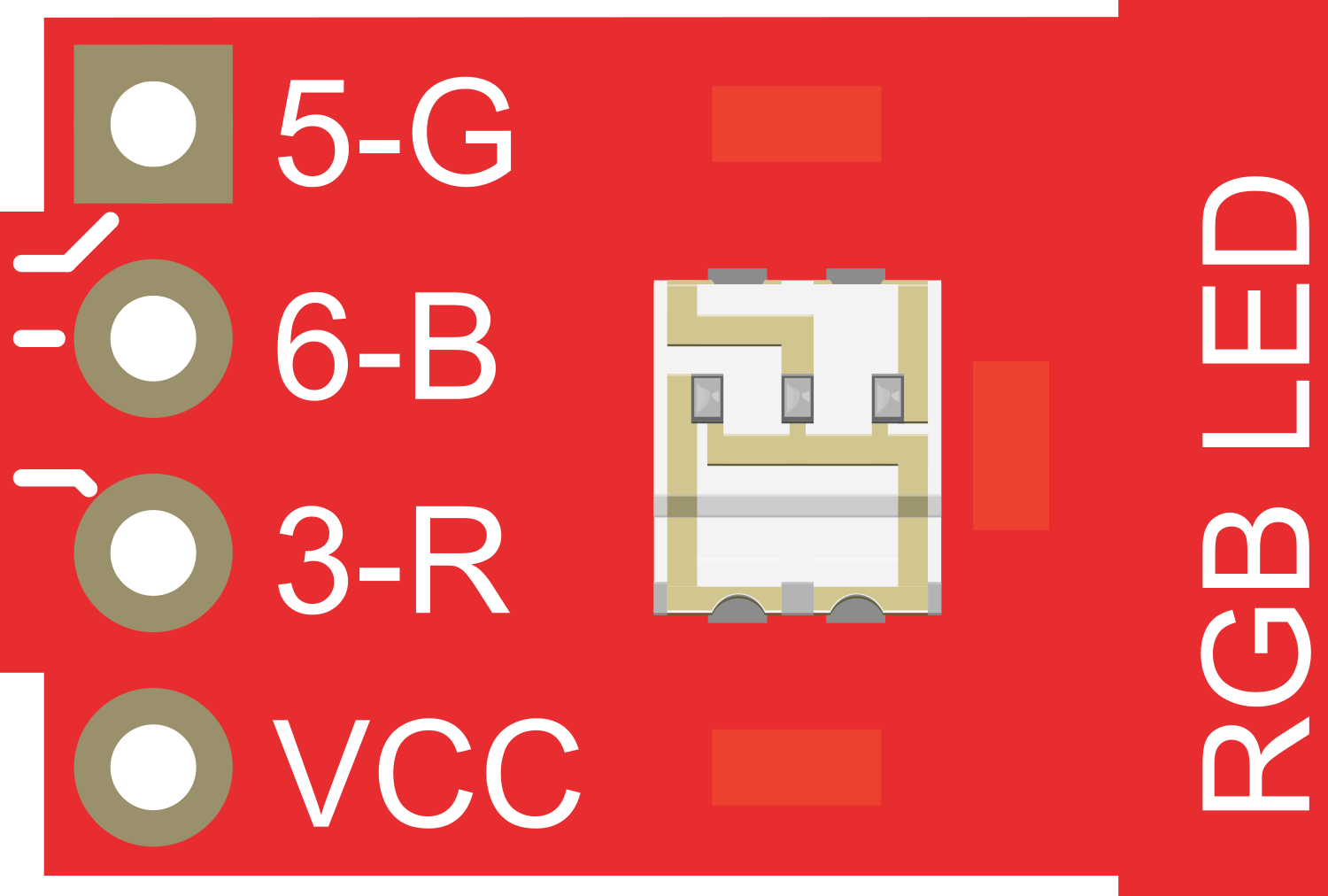
Pin Configuration
| Pin Number | Description |
|---|---|
| 1 | Red LED Anode |
| 2 | Green LED Anode |
| 3 | Blue LED Anode |
| 4 | Common Cathode (GND) |
Usage Instructions
Connecting the RGB LED to Arduino Pro Mini
- Connect the common cathode (pin 4) of the RGB LED to the GND pin on the Arduino Pro Mini.
- Connect the red anode (pin 1) to a PWM-capable digital pin on the Arduino Pro Mini.
- Repeat the above step for the green (pin 2) and blue (pin 3) anodes, each to separate PWM-capable pins.
Programming the RGB LED
To control the RGB LED, you will need to use PWM signals to adjust the brightness of each color channel. Here is a simple Arduino sketch that cycles through colors on the RGB LED:
// Define the RGB LED pins
const int RED_PIN = 9;   // Replace with your actual pin number
const int GREEN_PIN = 10; // Replace with your actual pin number
const int BLUE_PIN = 11;  // Replace with your actual pin number

void setup() {
  // Set the RGB LED pins to output mode
  pinMode(RED_PIN, OUTPUT);
  pinMode(GREEN_PIN, OUTPUT);
  pinMode(BLUE_PIN, OUTPUT);
}

void loop() {
  // Cycle through colors
  setColor(255, 0, 0); // Red
  delay(1000);
  setColor(0, 255, 0); // Green
  delay(1000);
  setColor(0, 0, 255); // Blue
  delay(1000);
}

void setColor(int redValue, int greenValue, int blueValue) {
  // Use PWM to set the color
  analogWrite(RED_PIN, redValue);
  analogWrite(GREEN_PIN, greenValue);
  analogWrite(BLUE_PIN, blueValue);
}
Best Practices
- Always use current-limiting resistors with each anode to prevent damage to the LED.
- Avoid setting the PWM value to the maximum for extended periods to prolong the life of the LED.
- Use heat sinks if operating the LED at high brightness levels for a long time.
Troubleshooting and FAQs
Common Issues
- LED not lighting up: Ensure that the pins are correctly connected and that the Arduino Pro Mini is powered.
- Incorrect colors: Verify that the anode pins are connected to the correct PWM pins on the Arduino Pro Mini.
- Dim LED: Check if the current-limiting resistors are of the correct value and that the PWM values are set appropriately.
FAQs
Q: Can I use the ProtoSnap - Pro Mini - RGB LED with a 5V supply? A: Yes, the RGB LED can operate with a supply voltage of up to 5V, but ensure that the current-limiting resistors are adjusted accordingly.
Q: How do I create different colors? A: By varying the PWM values for each color channel, you can mix red, green, and blue to create different colors. For example, to create yellow, you would set both the red and green channels to a high PWM value while keeping the blue channel low.
Q: What is the purpose of current-limiting resistors? A: Current-limiting resistors prevent excessive current from flowing through the LED, which could otherwise lead to overheating and damage.
For further assistance or inquiries, please refer to the manufacturer's support resources or community forums dedicated to Arduino and LED projects.