How to Use 300W 20A Buck Converter: Examples, Pinouts, and Specs
Introduction
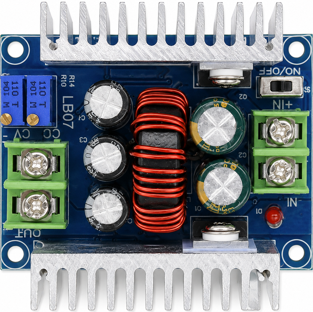
The 300W 20A Buck Converter is a high-power DC-DC step-down voltage regulator designed to efficiently convert a higher input voltage to a lower output voltage. With a maximum power rating of 300 watts and a current capacity of up to 20 amps, this converter is ideal for applications requiring high efficiency and stable voltage regulation. It is commonly used in battery charging systems, LED drivers, motor controllers, and other power supply applications.
Explore Projects Built with 300W 20A Buck Converter


Explore Projects Built with 300W 20A Buck Converter
Common Applications:
- Powering high-current devices such as motors or LED arrays
- Battery charging for lithium-ion, lead-acid, or other rechargeable batteries
- Voltage regulation in renewable energy systems (e.g., solar panels)
- Step-down voltage conversion for automotive or industrial electronics
Technical Specifications
Below are the key technical details of the 300W 20A Buck Converter:
| Parameter | Value |
|---|---|
| Input Voltage Range | 6V to 40V |
| Output Voltage Range | 1.2V to 36V (adjustable) |
| Maximum Output Current | 20A |
| Maximum Output Power | 300W |
| Efficiency | Up to 95% (depending on load) |
| Switching Frequency | 150 kHz |
| Operating Temperature | -40°C to +85°C |
| Dimensions | ~60mm x 52mm x 22mm |
Pin Configuration and Descriptions
The 300W 20A Buck Converter typically has the following input/output terminals:
| Pin/Terminal | Label | Description |
|---|---|---|
| Input (+) | VIN+ | Positive input voltage terminal (6V to 40V) |
| Input (-) | VIN- | Negative input voltage terminal (ground) |
| Output (+) | VOUT+ | Positive output voltage terminal (1.2V to 36V) |
| Output (-) | VOUT- | Negative output voltage terminal (ground) |
| Adjustment Potentiometer | - | Used to adjust the output voltage level |
Usage Instructions
How to Use the 300W 20A Buck Converter in a Circuit
Connect the Input Voltage:
- Connect the positive terminal of your DC power source to the
VIN+pin. - Connect the negative terminal of your DC power source to the
VIN-pin. - Ensure the input voltage is within the specified range (6V to 40V).
- Connect the positive terminal of your DC power source to the
Connect the Load:
- Connect the positive terminal of your load to the
VOUT+pin. - Connect the negative terminal of your load to the
VOUT-pin.
- Connect the positive terminal of your load to the
Adjust the Output Voltage:
- Use the onboard potentiometer to set the desired output voltage.
- Turn the potentiometer clockwise to increase the output voltage or counterclockwise to decrease it.
- Use a multimeter to measure the output voltage for precise adjustment.
Verify Connections:
- Double-check all connections to ensure proper polarity and secure wiring.
- Avoid short circuits between input and output terminals.
Power On:
- Turn on the input power supply and verify that the output voltage matches your desired setting.
Important Considerations and Best Practices
- Heat Dissipation: At high power levels, the converter may generate significant heat. Use an appropriate heatsink or active cooling (e.g., a fan) to prevent overheating.
- Current Limitation: Ensure the load does not exceed the maximum current rating of 20A to avoid damage.
- Input Voltage Margin: Always maintain the input voltage at least 2V higher than the desired output voltage for proper operation.
- Polarity Protection: Double-check the polarity of the input and output connections to prevent damage to the module.
Example: Using the Buck Converter with an Arduino UNO
The 300W 20A Buck Converter can be used to power an Arduino UNO by stepping down a higher voltage (e.g., 12V) to 5V. Below is an example circuit and Arduino code to blink an LED:
Circuit Setup:
- Connect a 12V DC power source to the
VIN+andVIN-terminals of the buck converter. - Adjust the output voltage to 5V using the potentiometer.
- Connect the
VOUT+terminal to the Arduino's 5V pin and theVOUT-terminal to the Arduino's GND pin. - Connect an LED to pin 13 of the Arduino with a 220-ohm resistor in series.
Arduino Code:
// Simple LED Blink Example
// This code blinks an LED connected to pin 13 of the Arduino UNO.

void setup() {
  pinMode(13, OUTPUT); // Set pin 13 as an output
}

void loop() {
  digitalWrite(13, HIGH); // Turn the LED on
  delay(1000);            // Wait for 1 second
  digitalWrite(13, LOW);  // Turn the LED off
  delay(1000);            // Wait for 1 second
}
Troubleshooting and FAQs
Common Issues and Solutions
No Output Voltage:
- Cause: Incorrect input connections or insufficient input voltage.
- Solution: Verify the input voltage is within the specified range and check the polarity of the connections.
Output Voltage Fluctuates:
- Cause: Load exceeds the maximum current rating or unstable input voltage.
- Solution: Reduce the load current or stabilize the input voltage source.
Overheating:
- Cause: High power operation without adequate cooling.
- Solution: Attach a heatsink or use active cooling to dissipate heat.
Cannot Adjust Output Voltage:
- Cause: Faulty potentiometer or incorrect adjustment procedure.
- Solution: Ensure the potentiometer is functional and adjust it slowly while monitoring the output voltage.
FAQs
Q1: Can I use this converter to charge a 12V battery?
A1: Yes, but ensure the output voltage is set slightly higher than the battery's nominal voltage (e.g., 13.8V for a 12V lead-acid battery). Monitor the charging current to avoid overcharging.
Q2: What happens if I reverse the input polarity?
A2: This module does not have built-in reverse polarity protection. Reversing the input polarity may damage the converter. Always double-check connections before powering on.
Q3: Can I use this converter with an AC power source?
A3: No, this is a DC-DC converter. You must use a DC power source within the specified input voltage range.
Q4: Is the output voltage stable under varying loads?
A4: Yes, the converter is designed to provide stable output voltage under varying load conditions, as long as the load does not exceed the maximum current rating.
By following this documentation, you can effectively use the 300W 20A Buck Converter in your projects while ensuring safe and reliable operation.