Cirkit Designer Logo
Cirkit Designer
Your all-in-one circuit design IDE
Home / 
Component Documentation

How to Use SK9822: Examples, Pinouts, and Specs

Image of SK9822
Cirkit Designer LogoDesign with SK9822 in Cirkit Designer

Introduction

The SK9822 is a digital RGB LED driver designed for precise control of individual LEDs' color and brightness. It features a two-wire interface (data and clock), enabling fast and reliable communication. This component is widely used in applications such as decorative lighting, LED displays, and dynamic animations. Its ability to control each LED independently makes it ideal for creating complex lighting effects with high precision.

Common applications include:

  • Decorative and architectural lighting
  • LED displays and signage
  • Wearable electronics
  • Gaming peripherals and PC case lighting
  • Animated light shows and art installations

Explore Projects Built with SK9822

Use Cirkit Designer to design, explore, and prototype these projects online. Some projects support real-time simulation. Click "Open Project" to start designing instantly!
Satellite-Based Timing and Navigation System with SDR and Atomic Clock Synchronization
Image of GPS 시스템 측정 구성도_Confirm: A project utilizing SK9822 in a practical application
This circuit appears to be a complex system involving power supply management, GPS and timing synchronization, and data communication. It includes a SI-TEX G1 Satellite Compass for GPS data, an XHTF1021 Atomic Rubidium Clock for precise timing, and Ettus USRP B200 units for software-defined radio communication. Power is supplied through various SMPS units and distributed via terminal blocks and DC jacks. Data communication is facilitated by Beelink MINI S12 N95 computers, RS232 splitters, and a 1000BASE-T Media Converter for network connectivity. RF Directional Couplers are used to interface antennas with the USRP units, and the entire system is likely contained within cases for protection and organization.
Cirkit Designer LogoOpen Project in Cirkit Designer
Battery-Powered Emergency Alert System with NUCLEO-F072RB, SIM800L, and GPS NEO 6M
Image of women safety: A project utilizing SK9822 in a practical application
This circuit is an emergency alert system that uses a NUCLEO-F072RB microcontroller to send SMS alerts and make calls via a SIM800L GSM module, while obtaining location data from a GPS NEO 6M module. The system is powered by a Li-ion battery and includes a TP4056 module for battery charging and protection, with a rocker switch to control power to the microcontroller.
Cirkit Designer LogoOpen Project in Cirkit Designer
Battery-Powered Wi-Fi Controlled IR Sensor Array with ESP8266
Image of v3: A project utilizing SK9822 in a practical application
This circuit uses a WeMOS ESP8266 microcontroller to read data from two Sharp IR sensors through a 16-channel analog multiplexer. The system is powered by a 2x 18650 battery pack, and the multiplexer allows the microcontroller to select and read from multiple sensor inputs.
Cirkit Designer LogoOpen Project in Cirkit Designer
ESP32-Based Portable Smart Speaker with Audio Input Processing
Image of talkAI: A project utilizing SK9822 in a practical application
This circuit features two ESP32 microcontrollers configured for serial communication, with one ESP32's TX0 connected to the other's RX2, and vice versa. An INMP441 microphone is interfaced with one ESP32 for audio input, using I2S protocol with connections for serial clock (SCK), word select (WS), and serial data (SD). A Max98357 audio amplifier is connected to the other ESP32 to drive a loudspeaker, receiving I2S data (DIN), bit clock (BLCK), and left-right clock (LRC), and is powered by a lipo battery charger module.
Cirkit Designer LogoOpen Project in Cirkit Designer

Explore Projects Built with SK9822

Use Cirkit Designer to design, explore, and prototype these projects online. Some projects support real-time simulation. Click "Open Project" to start designing instantly!
Image of GPS 시스템 측정 구성도_Confirm: A project utilizing SK9822 in a practical application
Satellite-Based Timing and Navigation System with SDR and Atomic Clock Synchronization
This circuit appears to be a complex system involving power supply management, GPS and timing synchronization, and data communication. It includes a SI-TEX G1 Satellite Compass for GPS data, an XHTF1021 Atomic Rubidium Clock for precise timing, and Ettus USRP B200 units for software-defined radio communication. Power is supplied through various SMPS units and distributed via terminal blocks and DC jacks. Data communication is facilitated by Beelink MINI S12 N95 computers, RS232 splitters, and a 1000BASE-T Media Converter for network connectivity. RF Directional Couplers are used to interface antennas with the USRP units, and the entire system is likely contained within cases for protection and organization.
Cirkit Designer LogoOpen Project in Cirkit Designer
Image of women safety: A project utilizing SK9822 in a practical application
Battery-Powered Emergency Alert System with NUCLEO-F072RB, SIM800L, and GPS NEO 6M
This circuit is an emergency alert system that uses a NUCLEO-F072RB microcontroller to send SMS alerts and make calls via a SIM800L GSM module, while obtaining location data from a GPS NEO 6M module. The system is powered by a Li-ion battery and includes a TP4056 module for battery charging and protection, with a rocker switch to control power to the microcontroller.
Cirkit Designer LogoOpen Project in Cirkit Designer
Image of v3: A project utilizing SK9822 in a practical application
Battery-Powered Wi-Fi Controlled IR Sensor Array with ESP8266
This circuit uses a WeMOS ESP8266 microcontroller to read data from two Sharp IR sensors through a 16-channel analog multiplexer. The system is powered by a 2x 18650 battery pack, and the multiplexer allows the microcontroller to select and read from multiple sensor inputs.
Cirkit Designer LogoOpen Project in Cirkit Designer
Image of talkAI: A project utilizing SK9822 in a practical application
ESP32-Based Portable Smart Speaker with Audio Input Processing
This circuit features two ESP32 microcontrollers configured for serial communication, with one ESP32's TX0 connected to the other's RX2, and vice versa. An INMP441 microphone is interfaced with one ESP32 for audio input, using I2S protocol with connections for serial clock (SCK), word select (WS), and serial data (SD). A Max98357 audio amplifier is connected to the other ESP32 to drive a loudspeaker, receiving I2S data (DIN), bit clock (BLCK), and left-right clock (LRC), and is powered by a lipo battery charger module.
Cirkit Designer LogoOpen Project in Cirkit Designer

Technical Specifications

The SK9822 is a versatile and efficient LED driver with the following key specifications:

Parameter Value
Operating Voltage 4.5V to 5.5V
Data Protocol Two-wire (Data and Clock)
Maximum Clock Frequency 30 MHz
LED Channels 3 (Red, Green, Blue)
PWM Resolution 8-bit per channel (24-bit color)
Brightness Control 5-bit global brightness control
Operating Temperature -40°C to +85°C
Package Type SMD (Surface Mount Device)

Pin Configuration and Descriptions

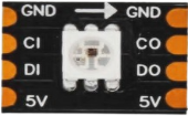
The SK9822 is typically integrated into LED strips or modules. Below is the pin configuration for a single SK9822 chip:

Pin Name Description
VDD Power supply input (4.5V to 5.5V)
GND Ground connection
DI Data input (receives data from the microcontroller)
CI Clock input (receives clock signal)
DO Data output (sends data to the next LED)
CO Clock output (sends clock to the next LED)

Usage Instructions

How to Use the SK9822 in a Circuit

  1. Power Supply: Connect the VDD pin to a 5V power source and the GND pin to ground. Ensure the power supply can handle the current requirements of all LEDs in the circuit.
  2. Data and Clock Lines: Connect the DI and CI pins to the microcontroller's data and clock output pins, respectively. Use the DO and CO pins to chain additional SK9822 LEDs.
  3. Bypass Capacitor: Place a 0.1 µF ceramic capacitor between VDD and GND near each SK9822 chip to stabilize the power supply.
  4. Termination Resistor: Add a 330Ω resistor in series with the data and clock lines to reduce signal reflections and noise.

Important Considerations and Best Practices

  • Signal Integrity: Keep the data and clock lines as short as possible to minimize signal degradation, especially at high clock frequencies.
  • Power Distribution: For long LED strips, inject power at multiple points to prevent voltage drops.
  • Heat Management: Ensure adequate ventilation or heat dissipation for high-density LED setups.
  • Data Timing: The SK9822 requires precise timing for data and clock signals. Refer to the datasheet for timing diagrams if needed.

Example Code for Arduino UNO

Below is an example of how to control an SK9822 LED strip using an Arduino UNO and the Adafruit DotStar library (compatible with SK9822):

#include <Adafruit_DotStar.h>
#include <SPI.h>

// Define the number of LEDs in the strip
#define NUM_LEDS 30

// Define data and clock pins
#define DATAPIN 4
#define CLOCKPIN 5

// Create an instance of the DotStar object
Adafruit_DotStar strip = Adafruit_DotStar(NUM_LEDS, DATAPIN, CLOCKPIN, DOTSTAR_BRG);

void setup() {
  strip.begin();  // Initialize the LED strip
  strip.show();   // Turn off all LEDs initially
}

void loop() {
  // Example: Cycle through red, green, and blue colors
  for (int i = 0; i < NUM_LEDS; i++) {
    strip.setPixelColor(i, 255, 0, 0);  // Set LED to red
  }
  strip.show();  // Update the strip
  delay(500);    // Wait for 500ms

  for (int i = 0; i < NUM_LEDS; i++) {
    strip.setPixelColor(i, 0, 255, 0);  // Set LED to green
  }
  strip.show();  // Update the strip
  delay(500);    // Wait for 500ms

  for (int i = 0; i < NUM_LEDS; i++) {
    strip.setPixelColor(i, 0, 0, 255);  // Set LED to blue
  }
  strip.show();  // Update the strip
  delay(500);    // Wait for 500ms
}

Troubleshooting and FAQs

Common Issues and Solutions

  1. LEDs Not Lighting Up:

    • Verify the power supply voltage (4.5V to 5.5V) and ensure it can handle the current demand.
    • Check the connections for the data and clock lines.
    • Ensure the microcontroller is correctly programmed and the library is installed.
  2. Flickering LEDs:

    • Add a 330Ω resistor in series with the data and clock lines to reduce noise.
    • Use a capacitor (e.g., 1000 µF) across the power supply to stabilize voltage.
  3. Incorrect Colors:

    • Ensure the data format matches the SK9822's expected protocol (e.g., BRG or RGB).
    • Check for timing issues in the microcontroller's code.
  4. Signal Degradation in Long Strips:

    • Use a level shifter to boost the data and clock signals.
    • Inject power at multiple points along the strip.

FAQs

Q: Can I control the SK9822 with a Raspberry Pi?
A: Yes, the SK9822 can be controlled using the Raspberry Pi's SPI interface. Libraries such as rpi_ws281x or dotstar can be used.

Q: How many SK9822 LEDs can I chain together?
A: Theoretically, you can chain hundreds of LEDs, but practical limits depend on power supply capacity and signal integrity.

Q: What is the difference between SK9822 and WS2812?
A: The SK9822 uses a two-wire interface (data and clock) for more reliable communication, especially at high speeds, while the WS2812 uses a single-wire protocol.

Q: Do I need an external clock source for the SK9822?
A: No, the clock signal is provided by the microcontroller or controller driving the SK9822.