Cirkit Designer Logo
Cirkit Designer
Your all-in-one circuit design IDE
Home / 
Component Documentation

How to Use TFT 128x128 Colour I2C Blue PCB: Examples, Pinouts, and Specs

Image of TFT 128x128 Colour I2C Blue PCB
Cirkit Designer LogoDesign with TFT 128x128 Colour I2C Blue PCB in Cirkit Designer

Introduction

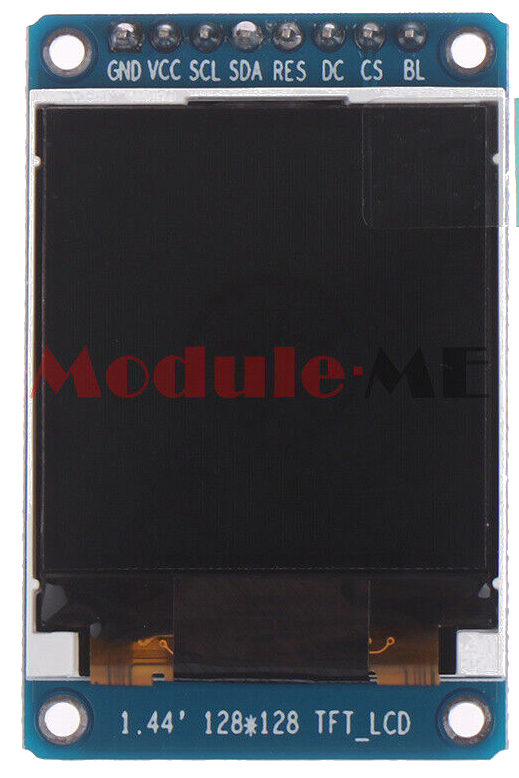
The TFT 128x128 Colour I2C Blue PCB is a compact and versatile display module suitable for adding a visual interface to your electronics projects. With a resolution of 128x128 pixels, it can display detailed graphics and text in a multitude of colors. The use of a Thin Film Transistor (TFT) technology ensures vivid colors and high pixel response times, making it ideal for dynamic visual displays.

Common applications include:

  • Portable instruments
  • DIY electronics
  • User interfaces for microcontroller projects
  • Wearable technology

Explore Projects Built with TFT 128x128 Colour I2C Blue PCB

Use Cirkit Designer to design, explore, and prototype these projects online. Some projects support real-time simulation. Click "Open Project" to start designing instantly!
Arduino Nano Controlled TFT Display with Multiple Pushbuttons
Image of rey: A project utilizing TFT 128x128 Colour I2C Blue PCB in a practical application
This circuit features an Arduino Nano microcontroller connected to a ST7735 128x128 1.44 TFT I2C Color display and multiple pushbuttons. The display is interfaced with the Arduino via digital pins for control signals and SPI pins for data transfer. The pushbuttons are connected to various digital and analog input pins on the Arduino, likely intended for user input to control the display or other functions within the code.
Cirkit Designer LogoOpen Project in Cirkit Designer
A-Star 32U4 Mini and I2C LCD Screen Battery-Powered Display
Image of lcd disolay: A project utilizing TFT 128x128 Colour I2C Blue PCB in a practical application
This circuit features an A-Star 32U4 Mini microcontroller connected to a 16x2 I2C LCD screen. The microcontroller provides power and ground to the LCD, and communicates with it via the I2C protocol using the A4 (SDA) and A5 (SCL) pins.
Cirkit Designer LogoOpen Project in Cirkit Designer
T-Beam with I2C OLED Display Interface
Image of MQTT_Node: A project utilizing TFT 128x128 Colour I2C Blue PCB in a practical application
This circuit connects a T-Beam microcontroller board with an OLED 128x64 I2C Monochrome Display. The T-Beam's I2C pins (SDA and SCL) are wired to the corresponding SDA and SCK pins on the OLED display, allowing for communication between the microcontroller and the display. Power and ground connections are also established, with the display's VDD connected to the T-Beam's 3V3 output, and GND to GND, to complete the power circuit for the display.
Cirkit Designer LogoOpen Project in Cirkit Designer
Arduino UNO Controlled TCS3200 Color Sensor with I2C LCD Display
Image of CeledonioT3: A project utilizing TFT 128x128 Colour I2C Blue PCB in a practical application
This circuit features an Arduino UNO microcontroller interfaced with a TCS3200 color sensor and an I2C LCD 16x2 display. The TCS3200 color sensor's output is connected to the Arduino's digital pin D12, and its frequency scaling pins (S0-S3) are connected to digital pins D8-D11 for configuration. The LCD display communicates with the Arduino via the I2C protocol, using A4 (SDA) and A5 (SCL) for data transfer, allowing the system to display color readings or other information from the sensor.
Cirkit Designer LogoOpen Project in Cirkit Designer

Explore Projects Built with TFT 128x128 Colour I2C Blue PCB

Use Cirkit Designer to design, explore, and prototype these projects online. Some projects support real-time simulation. Click "Open Project" to start designing instantly!
Image of rey: A project utilizing TFT 128x128 Colour I2C Blue PCB in a practical application
Arduino Nano Controlled TFT Display with Multiple Pushbuttons
This circuit features an Arduino Nano microcontroller connected to a ST7735 128x128 1.44 TFT I2C Color display and multiple pushbuttons. The display is interfaced with the Arduino via digital pins for control signals and SPI pins for data transfer. The pushbuttons are connected to various digital and analog input pins on the Arduino, likely intended for user input to control the display or other functions within the code.
Cirkit Designer LogoOpen Project in Cirkit Designer
Image of lcd disolay: A project utilizing TFT 128x128 Colour I2C Blue PCB in a practical application
A-Star 32U4 Mini and I2C LCD Screen Battery-Powered Display
This circuit features an A-Star 32U4 Mini microcontroller connected to a 16x2 I2C LCD screen. The microcontroller provides power and ground to the LCD, and communicates with it via the I2C protocol using the A4 (SDA) and A5 (SCL) pins.
Cirkit Designer LogoOpen Project in Cirkit Designer
Image of MQTT_Node: A project utilizing TFT 128x128 Colour I2C Blue PCB in a practical application
T-Beam with I2C OLED Display Interface
This circuit connects a T-Beam microcontroller board with an OLED 128x64 I2C Monochrome Display. The T-Beam's I2C pins (SDA and SCL) are wired to the corresponding SDA and SCK pins on the OLED display, allowing for communication between the microcontroller and the display. Power and ground connections are also established, with the display's VDD connected to the T-Beam's 3V3 output, and GND to GND, to complete the power circuit for the display.
Cirkit Designer LogoOpen Project in Cirkit Designer
Image of CeledonioT3: A project utilizing TFT 128x128 Colour I2C Blue PCB in a practical application
Arduino UNO Controlled TCS3200 Color Sensor with I2C LCD Display
This circuit features an Arduino UNO microcontroller interfaced with a TCS3200 color sensor and an I2C LCD 16x2 display. The TCS3200 color sensor's output is connected to the Arduino's digital pin D12, and its frequency scaling pins (S0-S3) are connected to digital pins D8-D11 for configuration. The LCD display communicates with the Arduino via the I2C protocol, using A4 (SDA) and A5 (SCL) for data transfer, allowing the system to display color readings or other information from the sensor.
Cirkit Designer LogoOpen Project in Cirkit Designer

Technical Specifications

Key Technical Details

  • Display Type: TFT
  • Resolution: 128x128 pixels
  • Interface: I2C
  • Operating Voltage: 3.3V - 5V
  • Logic Level: 3.3V (5V tolerant)
  • Active Area: 1.44 inches

Pin Configuration and Descriptions

Pin Number Pin Name Description
1 GND Ground
2 VCC Power supply (3.3V - 5V)
3 SCL I2C clock signal
4 SDA I2C data signal
5 RES Reset pin (active low)
6 DC Data/Command control pin
7 CS Chip Select (active low, optional)

Usage Instructions

Integration with a Circuit

  1. Power Connections: Connect the VCC pin to a 3.3V or 5V power supply, and the GND pin to the ground of your power source.
  2. I2C Communication: Connect the SCL and SDA pins to the corresponding I2C clock and data lines on your microcontroller.
  3. Reset Pin: The RES pin can be connected to a digital output on your microcontroller for resetting the display.
  4. Data/Command Control: The DC pin is used to switch between data and command modes and should be connected to a digital output on your microcontroller.
  5. Chip Select: The CS pin is optional and can be connected to a digital output on your microcontroller if multiple SPI devices are used.

Important Considerations and Best Practices

  • Ensure that the power supply is within the specified voltage range to prevent damage.
  • If using a 5V microcontroller, ensure that the logic level is compatible or use a level shifter.
  • Use pull-up resistors on the I2C lines if they are not built into the microcontroller.
  • Avoid exposing the display to direct sunlight or high temperatures to prevent damage.

Troubleshooting and FAQs

Common Issues

  • Display Not Powering On: Check the power connections and ensure the supply voltage is within the specified range.
  • No Data on Display: Verify that the I2C connections are correct and that the correct I2C address is being used in your code.
  • Garbled or Inconsistent Output: Ensure that the RES and DC pins are correctly connected and being controlled by the microcontroller.

Solutions and Tips for Troubleshooting

  • Double-check all connections and solder joints for continuity and shorts.
  • Use a logic analyzer or oscilloscope to verify the I2C signals.
  • Reset the display using the RES pin if the display becomes unresponsive.

FAQs

Q: What is the I2C address of the display? A: The I2C address for the display is typically 0x3C or 0x3D, but it can vary depending on the manufacturer. Consult the datasheet or use an I2C scanner sketch to determine the correct address.

Q: Can I use this display with a 5V microcontroller? A: Yes, but ensure that the logic levels are compatible or use a level shifter to prevent damage to the display.

Q: How can I control the brightness of the display? A: Brightness control is typically done through software by adjusting the backlight control register in the display's controller.

Example Code for Arduino UNO

Below is an example code snippet for initializing and displaying text on the TFT 128x128 Colour I2C Blue PCB using an Arduino UNO. This example assumes the use of a compatible TFT library.

#include <Wire.h>
#include <TFT.h> // Include the appropriate library for your display

// Define the pins
#define SCL_PIN A5
#define SDA_PIN A4
#define RES_PIN 9
#define DC_PIN  8
#define CS_PIN  10 // If not used, this can be set to -1

// Create an instance of the display
TFT myDisplay = TFT(CS_PIN, DC_PIN, RES_PIN);

void setup() {
  // Initialize the display
  myDisplay.begin();
  
  // Set the orientation of the display
  myDisplay.setRotation(1);
  
  // Clear the screen with a black background
  myDisplay.background(0, 0, 0);
  
  // Set the text color to white
  myDisplay.stroke(255, 255, 255);
  
  // Set the text size
  myDisplay.setTextSize(2);
  
  // Display a text on the screen
  myDisplay.text("Hello World!", 10, 10);
}

void loop() {
  // Main loop does nothing in this example
}

Remember to replace #include <TFT.h> with the actual library header for your specific TFT display, and ensure that the pin definitions match your wiring. The example code provided is a basic starting point and may require adjustments based on the specific library and display controller used.