How to Use laser receiver: Examples, Pinouts, and Specs
Introduction
The Laser Receiver by uknow (Part ID: uknow) is a device designed to detect and convert laser light into an electrical signal. This component is widely used in optical communication systems, laser-based sensors, and other applications requiring precise light detection. Its ability to accurately interpret laser signals makes it an essential component in modern electronics, particularly in systems requiring high-speed data transmission or precise optical sensing.
Explore Projects Built with laser receiver
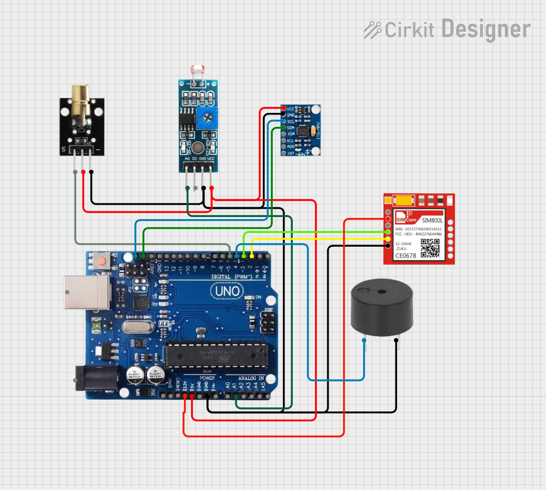
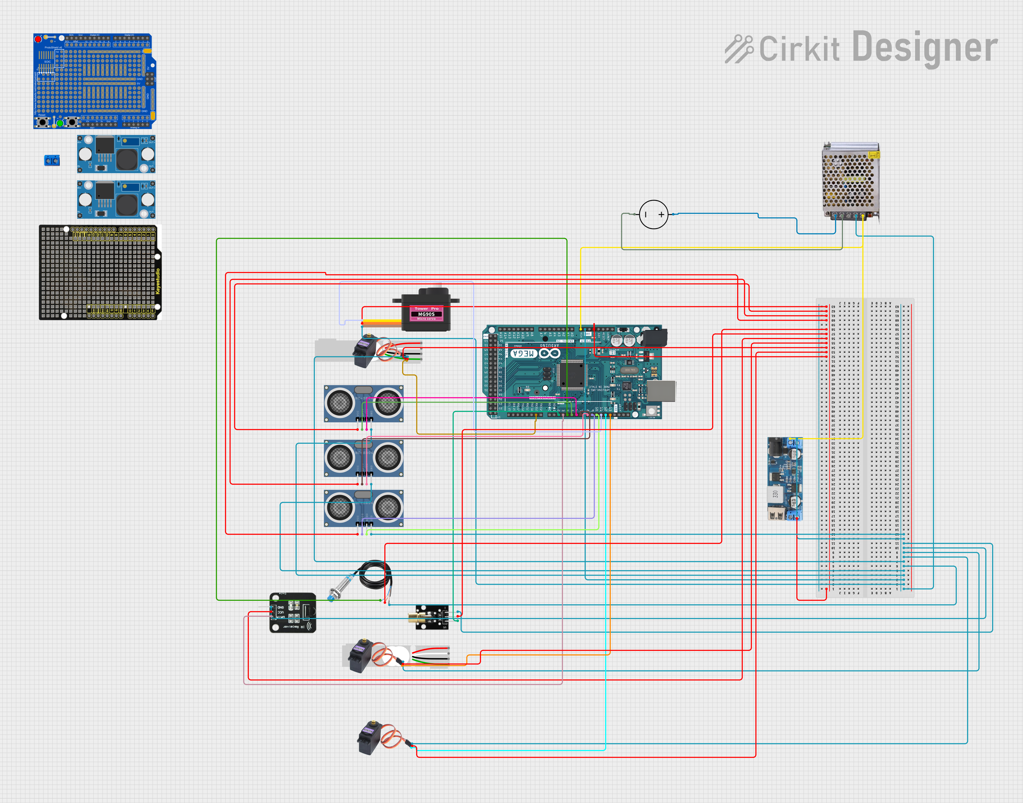
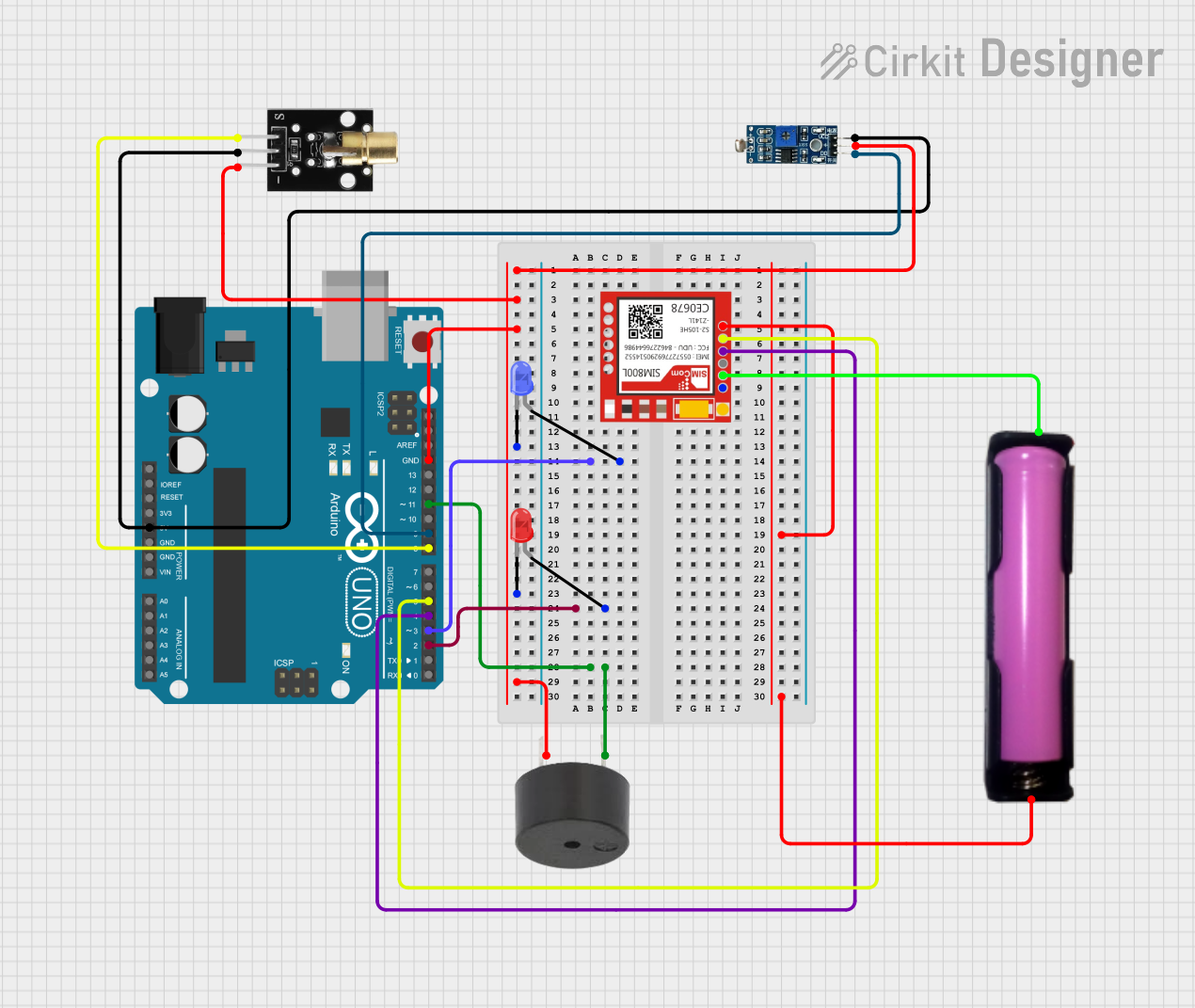
Explore Projects Built with laser receiver
Common Applications
- Optical communication systems (e.g., fiber optics)
- Laser-based distance measurement and ranging (LiDAR)
- Security systems (e.g., laser tripwires)
- Industrial automation and robotics
- Scientific instrumentation and research
Technical Specifications
The following table outlines the key technical details of the Laser Receiver:
| Parameter | Value |
|---|---|
| Manufacturer | uknow |
| Part ID | uknow |
| Operating Voltage | 3.3V to 5V |
| Operating Current | ≤ 20 mA |
| Wavelength Sensitivity | 400 nm to 1100 nm |
| Output Signal Type | Digital or Analog (depending on model) |
| Response Time | ≤ 10 µs |
| Operating Temperature | -20°C to 70°C |
| Dimensions | 10 mm x 8 mm x 5 mm |
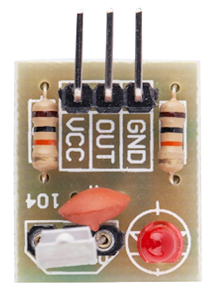
Pin Configuration
The Laser Receiver typically has three pins. The table below describes the pinout:
| Pin | Name | Description |
|---|---|---|
| 1 | VCC | Power supply input (3.3V to 5V) |
| 2 | GND | Ground connection |
| 3 | OUT | Output signal (digital or analog, depending on model) |
Usage Instructions
How to Use the Laser Receiver in a Circuit
- Power Supply: Connect the VCC pin to a 3.3V or 5V power source, depending on your system's requirements. Ensure the power supply is stable and within the specified range.
- Ground Connection: Connect the GND pin to the ground of your circuit.
- Output Signal: Connect the OUT pin to a microcontroller or other processing unit to read the output signal. If the receiver outputs an analog signal, you may need an ADC (Analog-to-Digital Converter) to process the data.
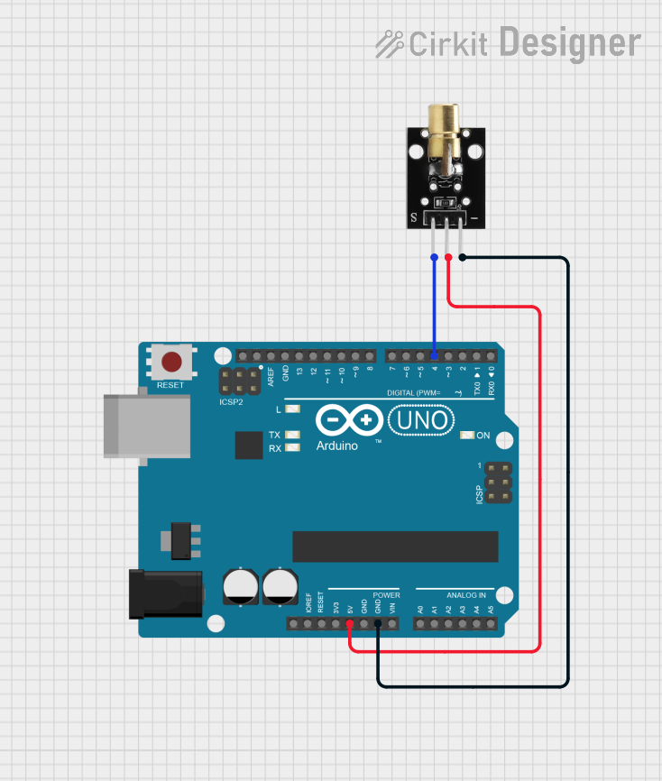
Example Circuit with Arduino UNO
Below is an example of how to connect the Laser Receiver to an Arduino UNO:
Circuit Connections
- VCC: Connect to the Arduino's 5V pin.
- GND: Connect to the Arduino's GND pin.
- OUT: Connect to a digital input pin (e.g., D2) on the Arduino.
Sample Code
// Laser Receiver Example Code
// This code reads the output of the laser receiver and prints the signal state
// to the Serial Monitor. Ensure the laser source is aligned with the receiver.

const int laserReceiverPin = 2; // Pin connected to the OUT pin of the receiver
int signalState = 0;            // Variable to store the signal state

void setup() {
  pinMode(laserReceiverPin, INPUT); // Set the laser receiver pin as input
  Serial.begin(9600);               // Initialize serial communication
}

void loop() {
  signalState = digitalRead(laserReceiverPin); // Read the signal state
  if (signalState == HIGH) {
    Serial.println("Laser detected!"); // Print message if laser is detected
  } else {
    Serial.println("No laser detected."); // Print message if no laser is detected
  }
  delay(500); // Wait for 500 ms before reading again
}
Important Considerations and Best Practices
- Alignment: Ensure the laser source is properly aligned with the receiver for optimal performance.
- Ambient Light: Minimize ambient light interference by using the receiver in controlled lighting conditions or employing optical filters.
- Power Supply: Use a stable power supply to avoid noise or fluctuations in the output signal.
- Heat Management: Avoid exposing the receiver to excessive heat, as it may affect performance or damage the component.
Troubleshooting and FAQs
Common Issues and Solutions
No Output Signal
- Cause: Misalignment between the laser source and receiver.
- Solution: Adjust the alignment of the laser source to ensure it directly hits the receiver.
Fluctuating Output
- Cause: Unstable power supply or excessive ambient light interference.
- Solution: Use a regulated power supply and reduce ambient light interference by shielding the receiver.
Slow Response
- Cause: Incorrect circuit design or excessive capacitance on the output pin.
- Solution: Verify the circuit design and minimize capacitance on the output pin.
Overheating
- Cause: Operating the receiver outside its specified temperature range.
- Solution: Ensure the receiver is used within the operating temperature range (-20°C to 70°C).
FAQs
Q1: Can the Laser Receiver detect any type of light?
A1: No, the Laser Receiver is optimized for laser light within the wavelength range of 400 nm to 1100 nm. It may not respond effectively to other light sources.
Q2: Can I use the Laser Receiver with a 3.3V microcontroller?
A2: Yes, the receiver operates within a voltage range of 3.3V to 5V, making it compatible with 3.3V microcontrollers.
Q3: How can I improve the accuracy of the Laser Receiver?
A3: Ensure proper alignment with the laser source, minimize ambient light interference, and use optical filters if necessary.
Q4: Is the output signal analog or digital?
A4: The output signal type depends on the specific model of the Laser Receiver. Refer to the product datasheet for details.
By following this documentation, users can effectively integrate the Laser Receiver into their projects and troubleshoot common issues with ease.