How to Use VL53-400: Examples, Pinouts, and Specs
Introduction
The VL53-400 is a time-of-flight (ToF) distance sensor manufactured by Wit Motion. It utilizes advanced laser technology to measure distances with high accuracy and speed. This sensor is ideal for applications requiring precise distance measurements, such as robotics, drones, industrial automation, and proximity sensing. Its compact design and reliable performance make it a popular choice for both hobbyists and professionals.
Explore Projects Built with VL53-400

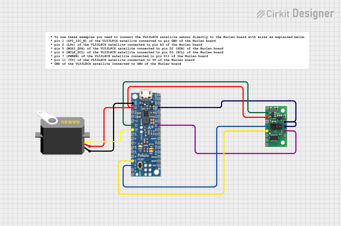

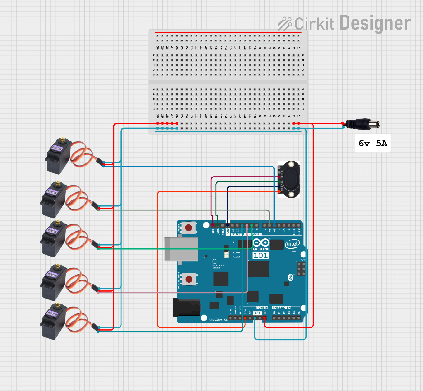
Explore Projects Built with VL53-400
Common Applications
- Obstacle detection in robotics and drones
- Proximity sensing in industrial automation
- Gesture recognition systems
- Distance measurement in smart devices
- Object tracking and positioning
Technical Specifications
The VL53-400 is designed to deliver accurate and fast distance measurements. Below are its key technical details:
| Parameter | Value |
|---|---|
| Operating Voltage | 2.8V to 3.3V |
| Operating Current | 20 mA (typical) |
| Measurement Range | 0.05 m to 4 m |
| Accuracy | ±3% (typical, depending on range) |
| Measurement Speed | Up to 50 Hz |
| Interface | I²C |
| Operating Temperature | -20°C to +70°C |
| Laser Wavelength | 940 nm (Class 1 laser) |
| Dimensions | 4.4 mm x 2.4 mm x 1.0 mm |
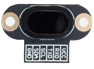
Pin Configuration and Descriptions
The VL53-400 has a simple pinout for easy integration into circuits. Below is the pin configuration:
| Pin Name | Pin Number | Description |
|---|---|---|
| VIN | 1 | Power supply input (2.8V to 3.3V) |
| GND | 2 | Ground |
| SDA | 3 | I²C data line |
| SCL | 4 | I²C clock line |
| XSHUT | 5 | Shutdown pin (active low) |
| GPIO1 | 6 | Interrupt output or programmable GPIO |
Usage Instructions
The VL53-400 is straightforward to use in a circuit, especially with microcontrollers like the Arduino UNO. Below are the steps to integrate and use the sensor:
Circuit Connection
- Connect the VIN pin to a 3.3V power supply.
- Connect the GND pin to the ground of your circuit.
- Connect the SDA pin to the SDA pin on your microcontroller (A4 on Arduino UNO).
- Connect the SCL pin to the SCL pin on your microcontroller (A5 on Arduino UNO).
- Optionally, connect the XSHUT pin to a GPIO pin on your microcontroller for enabling/disabling the sensor.
Important Considerations
- Ensure the operating voltage does not exceed 3.3V to avoid damaging the sensor.
- Use pull-up resistors (typically 4.7 kΩ) on the SDA and SCL lines for proper I²C communication.
- Avoid exposing the sensor to direct sunlight or reflective surfaces, as this may affect accuracy.
Sample Arduino Code
Below is an example of how to use the VL53-400 with an Arduino UNO:
#include <Wire.h>
#include <VL53L0X.h> // Include the VL53L0X library for ToF sensors

VL53L0X sensor; // Create an instance of the VL53L0X class

void setup() {
  Serial.begin(9600); // Initialize serial communication
  Wire.begin();       // Initialize I²C communication

  // Initialize the VL53-400 sensor
  if (!sensor.init()) {
    Serial.println("Failed to initialize VL53-400 sensor!");
    while (1); // Halt execution if initialization fails
  }

  sensor.setTimeout(500); // Set a timeout for measurements
  Serial.println("VL53-400 initialized successfully!");
}

void loop() {
  // Measure distance in millimeters
  uint16_t distance = sensor.readRangeSingleMillimeters();

  // Check for timeout errors
  if (sensor.timeoutOccurred()) {
    Serial.println("Sensor timeout occurred!");
  } else {
    Serial.print("Distance: ");
    Serial.print(distance);
    Serial.println(" mm");
  }

  delay(100); // Wait 100 ms before the next measurement
}
Notes on the Code
- The
VL53L0Xlibrary is used for communication with the sensor. Install it via the Arduino Library Manager. - The
readRangeSingleMillimeters()function retrieves the distance in millimeters. - The
setTimeout()function ensures the program does not hang if the sensor fails to respond.
Troubleshooting and FAQs
Common Issues
Sensor not responding or initializing:
- Ensure the sensor is powered correctly (2.8V to 3.3V).
- Verify the I²C connections (SDA and SCL) and check for loose wires.
- Use pull-up resistors on the I²C lines if not already present.
Incorrect or fluctuating distance readings:
- Avoid reflective or transparent surfaces in the sensor's field of view.
- Ensure the sensor is not exposed to direct sunlight or strong ambient light.
- Check for obstructions near the sensor's laser emitter or receiver.
Timeout errors in the code:
- Verify the sensor's connection to the microcontroller.
- Ensure the
XSHUTpin is not held low, as this disables the sensor.
FAQs
Q: Can the VL53-400 measure distances beyond 4 meters?
A: No, the maximum measurement range of the VL53-400 is 4 meters. For longer ranges, consider other ToF sensors.
Q: Is the laser safe for human eyes?
A: Yes, the VL53-400 uses a Class 1 laser, which is safe under normal operating conditions.
Q: Can I use the VL53-400 with a 5V microcontroller?
A: Yes, but you must use a level shifter to step down the I²C signals to 3.3V to avoid damaging the sensor.
Q: How can I reduce noise in the distance readings?
A: Use averaging techniques in your code or implement a low-pass filter to smooth out the measurements.
By following this documentation, you can effectively integrate and use the VL53-400 sensor in your projects.