How to Use 2.42 inch 128x64 OLED: Examples, Pinouts, and Specs
Introduction
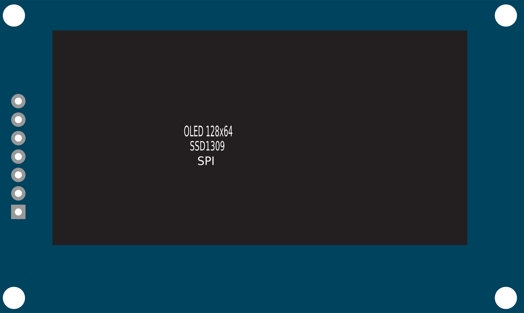
The 2.42 inch OLED display module is a compact and versatile screen suitable for a wide range of electronics projects. With its high contrast and readability, it is commonly used for displaying text, graphics, and animations. The Organic Light Emitting Diode (OLED) technology provides a bright display with a wide viewing angle, making it ideal for handheld devices, user interfaces, and information kiosks.
Explore Projects Built with 2.42 inch 128x64 OLED


Explore Projects Built with 2.42 inch 128x64 OLED
Common Applications and Use Cases
- DIY electronics projects
- User interfaces for embedded systems
- Portable instruments
- Data monitoring displays
- Wearable technology
Technical Specifications
Key Technical Details
- Display Type: OLED, Monochrome
- Screen Size: 2.42 inches
- Resolution: 128x64 pixels
- Viewing Angle: >160 degrees
- Operating Voltage: 3.3V to 5V
- Communication Interface: I2C/SPI (depending on model)
- Operating Temperature: -30°C to 70°C
Pin Configuration and Descriptions
| Pin Number | Pin Name | Description |
|---|---|---|
| 1 | GND | Ground |
| 2 | VCC | Power supply (3.3V - 5V) |
| 3 | SCL | Serial Clock Line (SPI/I2C) |
| 4 | SDA | Serial Data Line (I2C) or MOSI (SPI) |
| 5 | RES | Reset pin |
| 6 | DC | Data/Command control pin (SPI) |
| 7 | CS | Chip Select (SPI) |
Usage Instructions
How to Use the Component in a Circuit
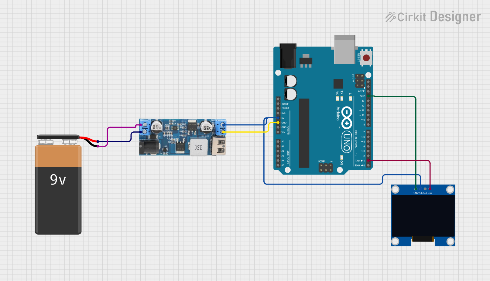
- Power Connections: Connect the VCC pin to a 3.3V or 5V power supply and the GND pin to the ground.
- Data Connections: For I2C communication, connect the SCL and SDA pins to the corresponding I2C pins on your microcontroller. For SPI communication, connect SCL (as SCK), SDA (as MOSI), DC, CS, and RES to the respective SPI pins.
- Initialization: Before using the display, it must be initialized with the correct settings for the communication protocol, display contrast, and other parameters.
Important Considerations and Best Practices
- Logic Level Matching: Ensure that the logic levels of the microcontroller match the display's voltage levels to prevent damage.
- Power Supply: Use a stable power supply to avoid any flickering or instability in the display.
- Current Draw: Be aware of the current draw when all pixels are lit and ensure your power supply can handle the load.
- Refresh Rate: To prevent ghosting, refresh the display periodically if displaying static images for extended periods.
Example Code for Arduino UNO
#include <Adafruit_GFX.h>
#include <Adafruit_SSD1306.h>

// OLED display TWI address
#define OLED_ADDR   0x3C
// Reset pin not used on 4-pin OLED module
#define RESET_PIN   -1

Adafruit_SSD1306 display(128, 64, &Wire, RESET_PIN);

void setup() {
  // Initialize with the I2C addr 0x3C (for the 128x64)
  if(!display.begin(SSD1306_SWITCHCAPVCC, OLED_ADDR)) {
    Serial.println(F("SSD1306 allocation failed"));
    for(;;);
  }
  display.display();
  delay(2000); // Pause for 2 seconds

  // Clear the buffer
  display.clearDisplay();

  // Draw a single pixel in white
  display.drawPixel(10, 10, WHITE);

  // Show the display buffer on the screen
  display.display();
  delay(2000); // Pause for 2 seconds
}

void loop() {
  // Put your main code here, to run repeatedly:
}
Troubleshooting and FAQs
Common Issues Users Might Face
- Display Not Turning On: Check the power connections and ensure the correct voltage is applied. Also, verify that the display is correctly initialized in the code.
- Garbled or No Display: Ensure that the I2C/SPI connections are correct and secure. Check for correct initialization and configuration in the software.
- Dim Display: Adjust the contrast setting in the initialization code or check for a low power supply voltage.
Solutions and Tips for Troubleshooting
- Check Connections: Double-check all wiring, especially the power and data lines.
- Use Example Code: Start with example code known to work and modify it incrementally.
- Serial Debugging: Use serial print statements to debug the initialization process and communication with the display.
FAQs
Q: Can the display be powered directly from an Arduino UNO? A: Yes, the display can be powered from the 3.3V or 5V output of an Arduino UNO.
Q: How do I adjust the brightness of the display? A: Brightness can be adjusted by changing the contrast settings in the display initialization code.
Q: Is it necessary to use a level shifter with a 5V microcontroller? A: It is recommended to use a level shifter if the display operates at 3.3V and the microcontroller at 5V to prevent damage to the display.