
How to Use Thumb Joystick: Examples, Pinouts, and Specs
 Design with Thumb Joystick in Cirkit Designer
Introduction
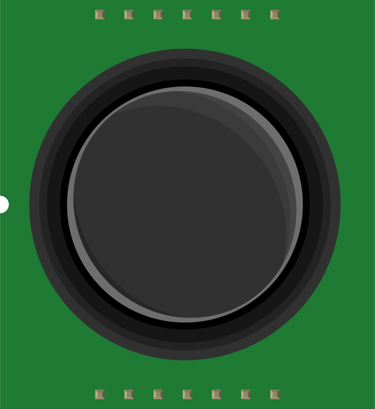
The Thumb Joystick (Manufacturer Part ID: COM-09032) by SparkFun Electronics is a compact, handheld input device designed for directional control and movement in electronic systems. It features a two-axis analog stick with a built-in pushbutton, making it ideal for applications requiring precise control, such as gaming, robotics, and user interface navigation. The joystick operates by detecting the position of the stick along the X and Y axes, outputting corresponding analog voltage levels.
Explore Projects Built with Thumb Joystick
 Open Project in Cirkit Designer
 Open Project in Cirkit Designer
 Open Project in Cirkit Designer
 Open Project in Cirkit Designer
Explore Projects Built with Thumb Joystick
Open Project in Cirkit DesignerOpen Project in Cirkit DesignerOpen Project in Cirkit DesignerOpen Project in Cirkit DesignerCommon Applications
- Game controllers and arcade systems
- Robotics and remote-controlled devices
- User interface navigation
- Camera gimbal control
- DIY electronics projects
Technical Specifications
The following table outlines the key technical details of the Thumb Joystick:
| Parameter | Specification |
|---|---|
| Manufacturer | SparkFun Electronics |
| Part ID | COM-09032 |
| Operating Voltage | 5V |
| Output Type | Analog (X and Y axes), Digital (SW) |
| Axes | 2 (X and Y) |
| Pushbutton | Integrated (momentary switch) |
| Dimensions | 26.5mm x 26.5mm x 15mm (approx.) |
| Mounting Type | PCB mount |
Pin Configuration
The Thumb Joystick has a 5-pin interface. The pinout is as follows:
| Pin | Name | Description |
|---|---|---|
| 1 | GND | Ground connection |
| 2 | +5V | Power supply (5V) |
| 3 | VRx | Analog output for X-axis position |
| 4 | VRy | Analog output for Y-axis position |
| 5 | SW | Digital output for the pushbutton (active LOW) |
Usage Instructions
Connecting the Thumb Joystick
- Power Supply: Connect the
+5Vpin to a 5V power source and theGNDpin to ground. - Analog Outputs: Connect the
VRxandVRypins to the analog input pins of your microcontroller (e.g., Arduino). - Pushbutton: Connect the
SWpin to a digital input pin of your microcontroller. Use a pull-up resistor if necessary, as the button output is active LOW.
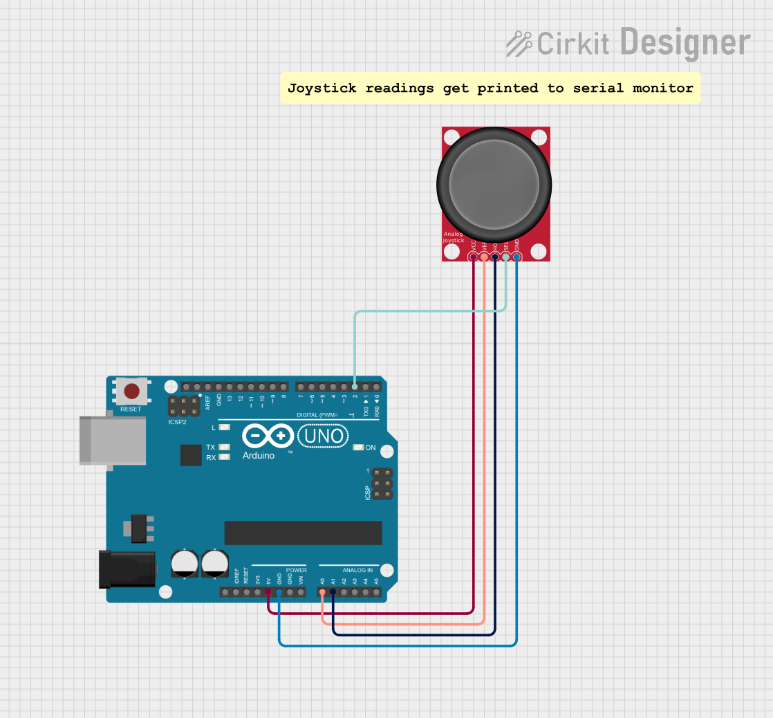
Example Circuit with Arduino UNO
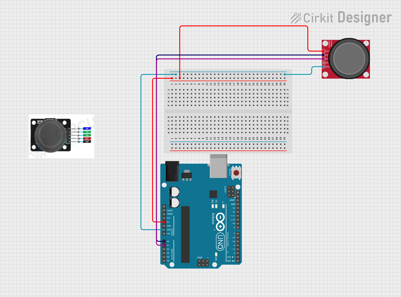
Below is an example of how to connect the Thumb Joystick to an Arduino UNO:
| Joystick Pin | Arduino Pin |
|---|---|
| GND | GND |
| +5V | 5V |
| VRx | A0 |
| VRy | A1 |
| SW | D2 |
Example Arduino Code
The following Arduino sketch reads the joystick's X and Y positions and detects button presses:
// Define pin connections
const int VRxPin = A0; // X-axis analog input
const int VRyPin = A1; // Y-axis analog input
const int SWPin = 2;   // Pushbutton digital input

void setup() {
  // Initialize serial communication for debugging
  Serial.begin(9600);

  // Configure the pushbutton pin as input with internal pull-up resistor
  pinMode(SWPin, INPUT_PULLUP);
}

void loop() {
  // Read the X and Y axis values (0-1023)
  int xValue = analogRead(VRxPin);
  int yValue = analogRead(VRyPin);

  // Read the pushbutton state (LOW when pressed)
  bool buttonPressed = (digitalRead(SWPin) == LOW);

  // Print the joystick values to the Serial Monitor
  Serial.print("X: ");
  Serial.print(xValue);
  Serial.print(" | Y: ");
  Serial.print(yValue);
  Serial.print(" | Button: ");
  Serial.println(buttonPressed ? "Pressed" : "Released");

  // Add a small delay for stability
  delay(100);
}
Best Practices
- Use a stable 5V power supply to ensure accurate analog readings.
- Avoid applying excessive force to the joystick to prevent damage.
- Use proper pull-up or pull-down resistors for the pushbutton if required by your circuit.
Troubleshooting and FAQs
Common Issues
Joystick Outputs Not Changing
- Cause: Loose or incorrect wiring.
- Solution: Verify all connections, especially the
VRxandVRypins.
Pushbutton Not Responding
- Cause: Missing pull-up resistor or incorrect pin configuration.
- Solution: Ensure the
SWpin is connected to a digital input with a pull-up resistor enabled.
Inconsistent Analog Readings
- Cause: Electrical noise or unstable power supply.
- Solution: Use decoupling capacitors near the power pins and ensure a clean power source.
FAQs
Q: Can the joystick be powered with 3.3V instead of 5V?
A: The joystick is designed for 5V operation. While it may function at 3.3V, the analog output range will be reduced, potentially affecting accuracy.
Q: How do I calibrate the joystick?
A: Read the analog values when the joystick is in its neutral position. Use these values as offsets in your code to ensure accurate readings.
Q: Is the pushbutton debounce handled automatically?
A: No, you need to implement software debounce in your code if required for your application.
By following this documentation, you can effectively integrate the SparkFun Thumb Joystick (COM-09032) into your projects for precise and reliable control.