Cirkit Designer Logo
Cirkit Designer
Your all-in-one circuit design IDE
Home / 
Component Documentation

How to Use 250W 12V ELECTRIC MOTOR BRUSH MOTOR DC: Examples, Pinouts, and Specs

Image of 250W 12V ELECTRIC MOTOR BRUSH MOTOR DC
Cirkit Designer LogoDesign with 250W 12V ELECTRIC MOTOR BRUSH MOTOR DC in Cirkit Designer

Introduction

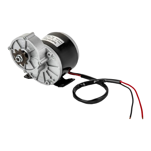
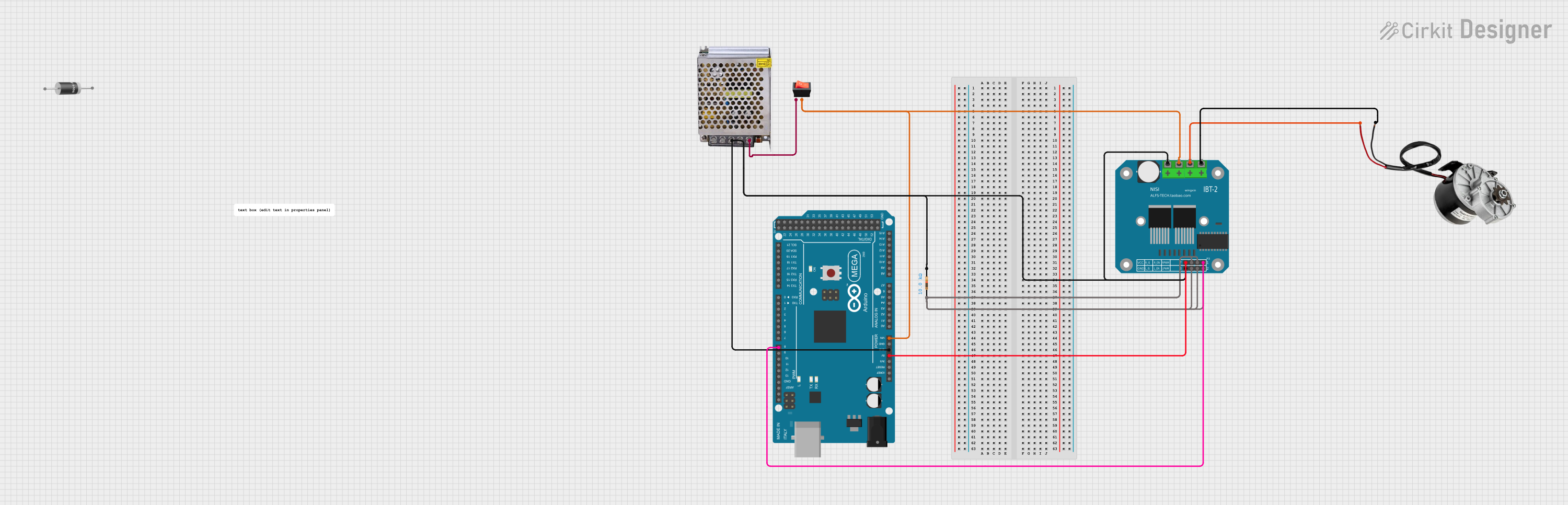
The 250W 12V Electric Brushed DC Motor is a robust and efficient motor designed for a variety of applications that require reliable and controlled motion. This motor is commonly used in electric scooters, bicycles, small vehicles, and DIY projects where a compact and powerful motor is needed.

Explore Projects Built with 250W 12V ELECTRIC MOTOR BRUSH MOTOR DC

Use Cirkit Designer to design, explore, and prototype these projects online. Some projects support real-time simulation. Click "Open Project" to start designing instantly!
Battery-Powered DC Motor Control System with Speed Regulation
Image of wheel chair: A project utilizing 250W 12V ELECTRIC MOTOR BRUSH MOTOR DC in a practical application
This circuit is a motor control system powered by two 12V batteries connected in series, with a 3-position switch to control a PWM motor speed controller. The system includes a pilot lamp for status indication and a NI-MH battery charger powered by an AC source.
Cirkit Designer LogoOpen Project in Cirkit Designer
Arduino Mega 2560-Controlled Robotic Actuators with Joystick and Pushbutton Interface
Image of Wheelchair: A project utilizing 250W 12V ELECTRIC MOTOR BRUSH MOTOR DC in a practical application
This is a motor control system featuring an Arduino Mega 2560 microcontroller that interfaces with L298N and BTS7960 motor drivers to control multiple DC motors and actuators. User inputs are provided through pushbuttons and a joystick, while power management is handled by 12V batteries and a buck converter, with a rocker switch for power control.
Cirkit Designer LogoOpen Project in Cirkit Designer
Bluetooth-Controlled Line Maker with Dual Motor and Pump Operation
Image of psm: A project utilizing 250W 12V ELECTRIC MOTOR BRUSH MOTOR DC in a practical application
This circuit is designed to control a line maker robot with two DC motors for movement and a pump for line marking. It features an Arduino UNO microcontroller for logic control, interfaced with a Bluetooth HC-06 module for wireless communication, and uses relays to switch the high-power components. The Arduino can operate in manual mode with button inputs or semi-automatic mode, receiving commands via Bluetooth to control the motors and pump.
Cirkit Designer LogoOpen Project in Cirkit Designer
Arduino Mega 2560 Controlled 250W DC Motor with BTS7960 Driver and Temperature-Based PWM
Image of DCmot+dst7960: A project utilizing 250W 12V ELECTRIC MOTOR BRUSH MOTOR DC in a practical application
This circuit is a motor control system that uses an Arduino Mega 2560 to regulate the speed of a 250W 12V DC motor via a BTS7960 motor driver. The Arduino reads temperature data from a sensor and adjusts the motor's PWM duty cycle accordingly, with power supplied by a 12V 5A power supply and controlled through a rocker switch.
Cirkit Designer LogoOpen Project in Cirkit Designer

Explore Projects Built with 250W 12V ELECTRIC MOTOR BRUSH MOTOR DC

Use Cirkit Designer to design, explore, and prototype these projects online. Some projects support real-time simulation. Click "Open Project" to start designing instantly!
Image of wheel chair: A project utilizing 250W 12V ELECTRIC MOTOR BRUSH MOTOR DC in a practical application
Battery-Powered DC Motor Control System with Speed Regulation
This circuit is a motor control system powered by two 12V batteries connected in series, with a 3-position switch to control a PWM motor speed controller. The system includes a pilot lamp for status indication and a NI-MH battery charger powered by an AC source.
Cirkit Designer LogoOpen Project in Cirkit Designer
Image of Wheelchair: A project utilizing 250W 12V ELECTRIC MOTOR BRUSH MOTOR DC in a practical application
Arduino Mega 2560-Controlled Robotic Actuators with Joystick and Pushbutton Interface
This is a motor control system featuring an Arduino Mega 2560 microcontroller that interfaces with L298N and BTS7960 motor drivers to control multiple DC motors and actuators. User inputs are provided through pushbuttons and a joystick, while power management is handled by 12V batteries and a buck converter, with a rocker switch for power control.
Cirkit Designer LogoOpen Project in Cirkit Designer
Image of psm: A project utilizing 250W 12V ELECTRIC MOTOR BRUSH MOTOR DC in a practical application
Bluetooth-Controlled Line Maker with Dual Motor and Pump Operation
This circuit is designed to control a line maker robot with two DC motors for movement and a pump for line marking. It features an Arduino UNO microcontroller for logic control, interfaced with a Bluetooth HC-06 module for wireless communication, and uses relays to switch the high-power components. The Arduino can operate in manual mode with button inputs or semi-automatic mode, receiving commands via Bluetooth to control the motors and pump.
Cirkit Designer LogoOpen Project in Cirkit Designer
Image of DCmot+dst7960: A project utilizing 250W 12V ELECTRIC MOTOR BRUSH MOTOR DC in a practical application
Arduino Mega 2560 Controlled 250W DC Motor with BTS7960 Driver and Temperature-Based PWM
This circuit is a motor control system that uses an Arduino Mega 2560 to regulate the speed of a 250W 12V DC motor via a BTS7960 motor driver. The Arduino reads temperature data from a sensor and adjusts the motor's PWM duty cycle accordingly, with power supplied by a 12V 5A power supply and controlled through a rocker switch.
Cirkit Designer LogoOpen Project in Cirkit Designer

Common Applications and Use Cases

  • Electric scooters and bicycles
  • Small electric vehicles
  • Robotics and automation projects
  • DIY electric-powered machines and tools

Technical Specifications

Key Technical Details

Specification Value
Power Rating 250 Watts
Nominal Voltage 12 Volts DC
No-load Current < 2.0 Amps
Load Current 20.8 Amps
Rated Speed 2750 RPM
Torque 0.80 Nm
Efficiency > 75%
Insulation Class Class B
Operating Temperature -10°C to +40°C

Pin Configuration and Descriptions

Since this is a motor, it does not have a pin configuration in the traditional sense. Instead, it has two terminals for power connection:

Terminal Description
+ Positive Lead
- Negative Lead

Usage Instructions

How to Use the Component in a Circuit

  1. Power Supply: Ensure that the power supply can handle the motor's nominal voltage of 12V and the load current of up to 20.8A.
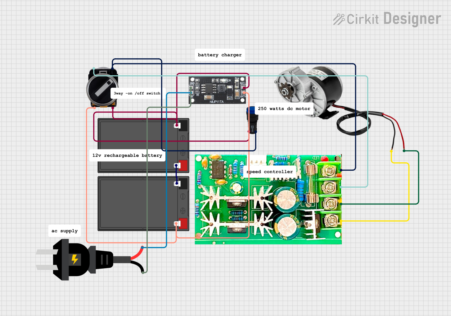
  2. Motor Controller: Use a suitable motor controller that can handle the power requirements and provide speed and direction control.
  3. Wiring: Connect the motor to the motor controller. The positive lead should go to the positive output of the controller, and the negative lead to the negative output.
  4. Activation: Use the motor controller to start, stop, and control the speed of the motor.

Important Considerations and Best Practices

  • Current Draw: Ensure that all components in the circuit can handle the maximum current draw of the motor.
  • Heat Dissipation: The motor can generate heat; provide adequate cooling if necessary.
  • Overload Protection: Use fuses or circuit breakers to protect against overcurrent conditions.
  • Mounting: Secure the motor firmly to prevent vibrations and ensure stable operation.

Troubleshooting and FAQs

Common Issues Users Might Face

  • Motor Does Not Start: Check power supply and connections. Ensure the motor controller is functioning correctly.
  • Excessive Noise or Vibration: Ensure the motor is mounted securely. Check for any obstructions or damage to the motor.
  • Overheating: Ensure adequate cooling and that the motor is not overloaded.

Solutions and Tips for Troubleshooting

  • Check Connections: Loose connections can cause intermittent or no operation.
  • Inspect for Damage: Physical damage to the motor or its terminals can cause failure.
  • Test Power Supply: Verify that the power supply is delivering the correct voltage and current.

FAQs

Q: Can I run this motor at a voltage higher than 12V? A: Running the motor at a higher voltage than its rated voltage can lead to overheating and reduced lifespan.

Q: What type of motor controller should I use? A: Use a DC motor controller that can handle at least 250W and 20.8A of current.

Q: How do I reverse the direction of the motor? A: Reverse the polarity of the motor connections, either manually or using a motor controller with this feature.

Q: Can this motor be used for regenerative braking? A: This motor does not support regenerative braking inherently. Additional circuitry and a compatible motor controller are required.

Q: Is this motor waterproof? A: Typically, brushed DC motors are not waterproof. Protect the motor from moisture to prevent damage.

Example Arduino UNO Code

This example demonstrates how to control the 250W 12V Electric Brushed DC Motor using an Arduino UNO and a compatible motor controller.

// Define motor control pins
const int motorEnablePin = 9; // PWM pin to enable motor
const int motorDirectionPin = 2; // Digital pin to control motor direction

void setup() {
  // Set motor control pins as outputs
  pinMode(motorEnablePin, OUTPUT);
  pinMode(motorDirectionPin, OUTPUT);
}

void loop() {
  // Set motor direction to forward
  digitalWrite(motorDirectionPin, HIGH);
  
  // Start the motor at half speed
  analogWrite(motorEnablePin, 127); // 50% duty cycle for PWM
  
  delay(5000); // Run for 5 seconds
  
  // Stop the motor
  analogWrite(motorEnablePin, 0);
  
  delay(2000); // Wait for 2 seconds
  
  // Set motor direction to reverse
  digitalWrite(motorDirectionPin, LOW);
  
  // Start the motor at full speed
  analogWrite(motorEnablePin, 255); // 100% duty cycle for PWM
  
  delay(5000); // Run for 5 seconds
  
  // Stop the motor
  analogWrite(motorEnablePin, 0);
  
  delay(2000); // Wait for 2 seconds
}

Note: The above code assumes the use of a motor controller that interfaces with the Arduino UNO. The motor controller must be capable of handling the motor's power requirements. Always refer to the motor controller's datasheet for wiring and programming instructions.