Cirkit Designer Logo
Cirkit Designer
Your all-in-one circuit design IDE
Home / 
Component Documentation

How to Use RAK 4631: Examples, Pinouts, and Specs

Image of RAK 4631
Cirkit Designer LogoDesign with RAK 4631 in Cirkit Designer

Introduction

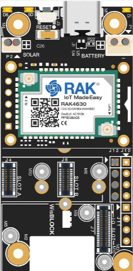
The RAK 4631 is a low-power, long-range LoRaWAN module designed for Internet of Things (IoT) applications. Manufactured by RAK under the WisBlock series, this module combines a compact design with advanced features such as integrated GPS and support for multiple communication protocols. It is ideal for applications requiring remote sensing, environmental monitoring, asset tracking, and other IoT solutions where low power consumption and long-range communication are critical.

Explore Projects Built with RAK 4631

Use Cirkit Designer to design, explore, and prototype these projects online. Some projects support real-time simulation. Click "Open Project" to start designing instantly!
Arduino 101 Based RFID and GSM Security System with I2C LCD Display and RTC
Image of id scanner with messaging system: A project utilizing RAK 4631 in a practical application
This circuit features an Arduino 101 microcontroller interfaced with an RFID-RC522 module for RFID reading, a GSM SIM900 module for cellular communication, a DS3231 Real Time Clock for timekeeping, and an I2C LCD screen for display. The Arduino controls a buzzer connected to its D7 pin and communicates with the GSM module via serial connection on pins D0/RX and D1/TX. The RFID, RTC, and LCD modules are powered by the Arduino's 5V and 3.3V outputs, and they use I2C (SCL/SDA) for communication, except for the RFID module which uses SPI (MISO/MOSI/SCK) and a digital pin for reset (D9).
Cirkit Designer LogoOpen Project in Cirkit Designer
Arduino UNO with 433MHz RF Module for Wireless Communication
Image of Receiver: A project utilizing RAK 4631 in a practical application
This circuit consists of an Arduino UNO connected to an RXN433MHz radio frequency module. The Arduino provides 5V power and ground to the RF module and is configured to communicate with it via digital pin D11. Additionally, a multimeter is connected with alligator clip cables to measure the voltage supplied to the RF module.
Cirkit Designer LogoOpen Project in Cirkit Designer
Arduino UNO Based RFID Time Tracking System with I2C LCD Display and RTC
Image of RFID arduino: A project utilizing RAK 4631 in a practical application
This circuit features an Arduino UNO microcontroller interfaced with an RFID-RC522 module, an I2C LCD Display, and a DS3231 Real-Time Clock (RTC). The Arduino communicates with the RFID reader and the RTC via SPI and I2C protocols, respectively, and displays information on the LCD. The purpose of this circuit is likely for a time-attendance system or access control where RFID tags are scanned, time-stamped by the RTC, and the event details are displayed on the LCD.
Cirkit Designer LogoOpen Project in Cirkit Designer
Battery-Powered Emergency Alert System with NUCLEO-F072RB, SIM800L, and GPS NEO 6M
Image of women safety: A project utilizing RAK 4631 in a practical application
This circuit is an emergency alert system that uses a NUCLEO-F072RB microcontroller to send SMS alerts and make calls via a SIM800L GSM module, while obtaining location data from a GPS NEO 6M module. The system is powered by a Li-ion battery and includes a TP4056 module for battery charging and protection, with a rocker switch to control power to the microcontroller.
Cirkit Designer LogoOpen Project in Cirkit Designer

Explore Projects Built with RAK 4631

Use Cirkit Designer to design, explore, and prototype these projects online. Some projects support real-time simulation. Click "Open Project" to start designing instantly!
Image of id scanner with messaging system: A project utilizing RAK 4631 in a practical application
Arduino 101 Based RFID and GSM Security System with I2C LCD Display and RTC
This circuit features an Arduino 101 microcontroller interfaced with an RFID-RC522 module for RFID reading, a GSM SIM900 module for cellular communication, a DS3231 Real Time Clock for timekeeping, and an I2C LCD screen for display. The Arduino controls a buzzer connected to its D7 pin and communicates with the GSM module via serial connection on pins D0/RX and D1/TX. The RFID, RTC, and LCD modules are powered by the Arduino's 5V and 3.3V outputs, and they use I2C (SCL/SDA) for communication, except for the RFID module which uses SPI (MISO/MOSI/SCK) and a digital pin for reset (D9).
Cirkit Designer LogoOpen Project in Cirkit Designer
Image of Receiver: A project utilizing RAK 4631 in a practical application
Arduino UNO with 433MHz RF Module for Wireless Communication
This circuit consists of an Arduino UNO connected to an RXN433MHz radio frequency module. The Arduino provides 5V power and ground to the RF module and is configured to communicate with it via digital pin D11. Additionally, a multimeter is connected with alligator clip cables to measure the voltage supplied to the RF module.
Cirkit Designer LogoOpen Project in Cirkit Designer
Image of RFID arduino: A project utilizing RAK 4631 in a practical application
Arduino UNO Based RFID Time Tracking System with I2C LCD Display and RTC
This circuit features an Arduino UNO microcontroller interfaced with an RFID-RC522 module, an I2C LCD Display, and a DS3231 Real-Time Clock (RTC). The Arduino communicates with the RFID reader and the RTC via SPI and I2C protocols, respectively, and displays information on the LCD. The purpose of this circuit is likely for a time-attendance system or access control where RFID tags are scanned, time-stamped by the RTC, and the event details are displayed on the LCD.
Cirkit Designer LogoOpen Project in Cirkit Designer
Image of women safety: A project utilizing RAK 4631 in a practical application
Battery-Powered Emergency Alert System with NUCLEO-F072RB, SIM800L, and GPS NEO 6M
This circuit is an emergency alert system that uses a NUCLEO-F072RB microcontroller to send SMS alerts and make calls via a SIM800L GSM module, while obtaining location data from a GPS NEO 6M module. The system is powered by a Li-ion battery and includes a TP4056 module for battery charging and protection, with a rocker switch to control power to the microcontroller.
Cirkit Designer LogoOpen Project in Cirkit Designer

Common Applications

  • Environmental monitoring (e.g., temperature, humidity, air quality)
  • Asset tracking and fleet management
  • Smart agriculture and precision farming
  • Industrial IoT (IIoT) applications
  • Smart cities (e.g., parking sensors, waste management)
  • Remote sensing and telemetry

Technical Specifications

Key Technical Details

Parameter Specification
Microcontroller Nordic nRF52840 (ARM Cortex-M4, 32-bit, 64 MHz)
LoRaWAN Module Semtech SX1262
Communication Protocols LoRaWAN, BLE 5.0, NFC
GPS Integrated Quectel L76-L GPS module
Operating Voltage 3.3V
Power Consumption Ultra-low power (sleep mode: ~2 µA)
Flash Memory 1 MB
RAM 256 KB
Frequency Bands 868 MHz (EU), 915 MHz (US), 923 MHz (AS)
Operating Temperature -40°C to +85°C
Dimensions 35 mm x 25 mm

Pin Configuration and Descriptions

The RAK 4631 module has a total of 40 pins, with the most commonly used pins described below:

Pin Number Pin Name Description
1 VCC Power supply input (3.3V)
2 GND Ground connection
3 GPIO1 General-purpose I/O pin
4 GPIO2 General-purpose I/O pin
5 UART_TX UART transmit pin
6 UART_RX UART receive pin
7 I2C_SCL I2C clock line
8 I2C_SDA I2C data line
9 SPI_MOSI SPI Master Out Slave In
10 SPI_MISO SPI Master In Slave Out
11 SPI_SCK SPI clock
12 SPI_CS SPI chip select
13 RESET Reset pin
14 ANT Antenna connection for LoRaWAN
15 GPS_TX GPS module transmit pin
16 GPS_RX GPS module receive pin

For a complete pinout, refer to the official RAK 4631 datasheet.

Usage Instructions

How to Use the RAK 4631 in a Circuit

  1. Power Supply: Connect the VCC pin to a 3.3V power source and GND to ground.
  2. Antenna: Attach a compatible LoRaWAN antenna to the ANT pin for optimal signal strength.
  3. Communication: Use UART, I2C, or SPI interfaces to communicate with the module, depending on your application.
  4. GPS: Connect the GPS_TX and GPS_RX pins to your microcontroller for GPS data.
  5. Programming: The RAK 4631 can be programmed using the Arduino IDE or PlatformIO. Install the necessary board definitions and libraries from the RAKwireless GitHub repository.

Important Considerations

  • Power Management: Use the module's low-power modes to extend battery life in IoT applications.
  • Antenna Placement: Ensure the antenna is placed away from metal surfaces or other obstructions to avoid signal interference.
  • Firmware Updates: Regularly update the firmware to access the latest features and bug fixes.
  • Regulatory Compliance: Ensure the frequency band used complies with local regulations (e.g., 868 MHz for Europe, 915 MHz for the US).

Example Code for Arduino UNO

Below is an example of how to send a LoRaWAN message using the RAK 4631 with the Arduino IDE:

#include <LoRa.h> // Include the LoRa library

// Define LoRa pins
#define LORA_SCK 5   // SPI clock
#define LORA_MISO 19 // SPI MISO
#define LORA_MOSI 27 // SPI MOSI
#define LORA_CS 18   // SPI chip select
#define LORA_RST 14  // Reset pin
#define LORA_IRQ 26  // IRQ pin

void setup() {
  // Initialize serial communication
  Serial.begin(9600);
  while (!Serial);

  // Initialize LoRa module
  Serial.println("Initializing LoRa...");
  if (!LoRa.begin(915E6)) { // Set frequency to 915 MHz
    Serial.println("LoRa initialization failed!");
    while (1);
  }
  Serial.println("LoRa initialized successfully.");
}

void loop() {
  // Send a test message
  Serial.println("Sending message...");
  LoRa.beginPacket();
  LoRa.print("Hello, LoRa!");
  LoRa.endPacket();

  // Wait 5 seconds before sending the next message
  delay(5000);
}

Note: Replace the pin definitions with the actual pins used in your setup. Ensure the LoRa library is installed in your Arduino IDE.

Troubleshooting and FAQs

Common Issues

  1. No LoRaWAN Signal Detected:

    • Cause: Incorrect antenna placement or frequency mismatch.
    • Solution: Verify the antenna connection and ensure the frequency band matches your region.
  2. Module Not Responding:

    • Cause: Incorrect power supply or wiring.
    • Solution: Check the power supply voltage (3.3V) and ensure all connections are secure.
  3. GPS Not Acquiring Signal:

    • Cause: Poor satellite visibility or interference.
    • Solution: Place the module in an open area with a clear view of the sky.
  4. High Power Consumption:

    • Cause: Module not in low-power mode.
    • Solution: Use the sleep mode feature to reduce power consumption.

FAQs

  • Q: Can the RAK 4631 be used with other microcontrollers?
    A: Yes, the RAK 4631 can interface with other microcontrollers via UART, I2C, or SPI.

  • Q: Is the RAK 4631 compatible with LoRaWAN gateways?
    A: Yes, it is fully compatible with standard LoRaWAN gateways.

  • Q: How do I update the firmware?
    A: Use the RAK DFU tool or the Arduino IDE to upload the latest firmware.

  • Q: Can I use the RAK 4631 for BLE applications?
    A: Yes, the module supports BLE 5.0 for short-range communication.

For additional support, refer to the official RAK documentation or community forums.