
How to Use Arduino Micro: Examples, Pinouts, and Specs
 Design with Arduino Micro in Cirkit Designer
Introduction
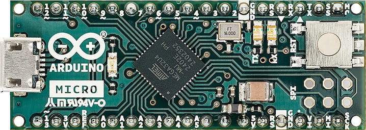
The Arduino Micro is a compact microcontroller board developed by Arduino, based on the ATmega32U4 microcontroller. It features built-in USB connectivity, making it an excellent choice for projects requiring direct communication with a computer. Its small form factor and versatile functionality make it ideal for embedded systems, wearable devices, and prototyping.
Explore Projects Built with Arduino Micro
 Open Project in Cirkit Designer
 Open Project in Cirkit Designer
 Open Project in Cirkit Designer
 Open Project in Cirkit Designer
Explore Projects Built with Arduino Micro
Open Project in Cirkit DesignerOpen Project in Cirkit DesignerOpen Project in Cirkit DesignerOpen Project in Cirkit DesignerCommon Applications
- USB-based projects (e.g., custom keyboards, mice, or game controllers)
- Embedded systems and IoT devices
- Wearable electronics
- Robotics and automation
- Prototyping for compact designs
Technical Specifications
The Arduino Micro is designed to provide robust performance in a small package. Below are its key technical details:
Key Specifications
| Parameter | Value |
|---|---|
| Microcontroller | ATmega32U4 |
| Operating Voltage | 5V |
| Input Voltage (VIN) | 7-12V |
| Digital I/O Pins | 20 (7 PWM outputs) |
| Analog Input Pins | 12 |
| DC Current per I/O Pin | 20 mA |
| Flash Memory | 32 KB (4 KB used by bootloader) |
| SRAM | 2.5 KB |
| EEPROM | 1 KB |
| Clock Speed | 16 MHz |
| USB Connectivity | Native USB (Micro USB port) |
| Dimensions | 48 mm x 18 mm |
Pin Configuration and Descriptions
The Arduino Micro has 24 pins, including digital, analog, and power pins. Below is a detailed pinout description:
Digital Pins
| Pin Number | Functionality | Description |
|---|---|---|
| D0 - D13 | Digital I/O | General-purpose digital input/output pins |
| D3, D5, D6, D9, D10, D11 | PWM Output | Pulse Width Modulation capable pins |
| D0, D1 | UART (RX/TX) | Serial communication pins |
| D2, D3 | External Interrupts | Interrupt-capable pins |
Analog Pins
| Pin Number | Functionality | Description |
|---|---|---|
| A0 - A11 | Analog Input | 10-bit ADC capable pins |
Power Pins
| Pin Name | Functionality | Description |
|---|---|---|
| VIN | Input Voltage | External power input (7-12V) |
| 5V | Regulated 5V Output | Provides 5V output |
| 3.3V | Regulated 3.3V Output | Provides 3.3V output |
| GND | Ground | Ground connection |
| IOREF | I/O Reference Voltage | Voltage reference for I/O pins |
| RESET | Reset | Resets the microcontroller |
Usage Instructions
The Arduino Micro is straightforward to use in a variety of projects. Below are the steps and best practices for integrating it into your designs.
Connecting the Arduino Micro
Powering the Board:
- Use the Micro USB port to power the board via a computer or USB adapter.
- Alternatively, supply 7-12V to the VIN pin for external power.
Programming the Board:
- Connect the Arduino Micro to your computer using a Micro USB cable.
- Open the Arduino IDE and select Arduino Micro under
Tools > Board. - Select the appropriate COM port under
Tools > Port. - Write or load your sketch and click Upload.
Using the Pins:
- Connect sensors, actuators, or other components to the digital and analog pins.
- Use the PWM pins for controlling devices like motors or LEDs with variable intensity.
Example Code: Blinking an LED
The following example demonstrates how to blink an LED connected to pin 13.
// Blink an LED connected to pin 13
// This example toggles the LED on and off every second.

void setup() {
  pinMode(13, OUTPUT); // Set pin 13 as an output
}

void loop() {
  digitalWrite(13, HIGH); // Turn the LED on
  delay(1000);            // Wait for 1 second
  digitalWrite(13, LOW);  // Turn the LED off
  delay(1000);            // Wait for 1 second
}
Best Practices
- Avoid exceeding the 20 mA current limit per I/O pin to prevent damage.
- Use external pull-up or pull-down resistors for stable digital input readings.
- When using the board in USB HID (Human Interface Device) mode, ensure proper USB communication handling in your code.
Troubleshooting and FAQs
Common Issues
The board is not recognized by the computer:
- Ensure the USB cable is functional and supports data transfer.
- Check that the correct COM port is selected in the Arduino IDE.
- Try reinstalling the Arduino drivers.
Sketch upload fails:
- Verify that the correct board and port are selected in the Arduino IDE.
- Press the RESET button on the board before uploading the sketch.
The board is not powering on:
- Confirm that the power source (USB or VIN) is supplying the correct voltage.
- Check for loose connections or damaged components.
FAQs
Q: Can the Arduino Micro act as a USB keyboard or mouse?
A: Yes, the ATmega32U4 microcontroller supports native USB communication, allowing the Arduino Micro to emulate USB HID devices like keyboards and mice.
Q: What is the maximum current the board can supply?
A: The 5V pin can supply up to 500 mA when powered via USB, but this depends on the USB port's capacity.
Q: Can I use the Arduino Micro with a battery?
A: Yes, you can connect a battery (7-12V) to the VIN pin or use a regulated 5V source on the 5V pin.
Q: How do I reset the board?
A: Press the RESET button on the board or connect the RESET pin to GND momentarily.
By following this documentation, you can effectively utilize the Arduino Micro in your projects and troubleshoot common issues with ease.