How to Use Orange Pi Zero 3: Examples, Pinouts, and Specs
Introduction
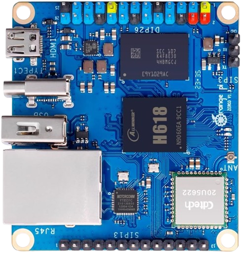
The Orange Pi Zero 3, manufactured by Shenzhen Xunlong Software, is a compact single-board computer (SBC) designed for versatility and performance. Featuring an Allwinner H618 quad-core processor, 1GB of RAM, and various connectivity options including Wi-Fi, Bluetooth, and Ethernet, this SBC is suitable for a wide range of applications from IoT projects to media centers.
Explore Projects Built with Orange Pi Zero 3
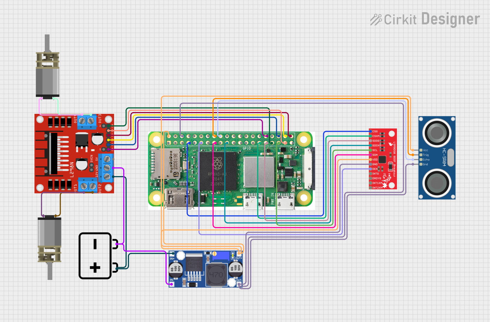
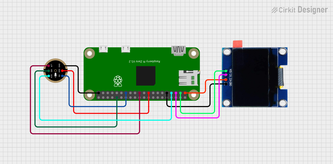

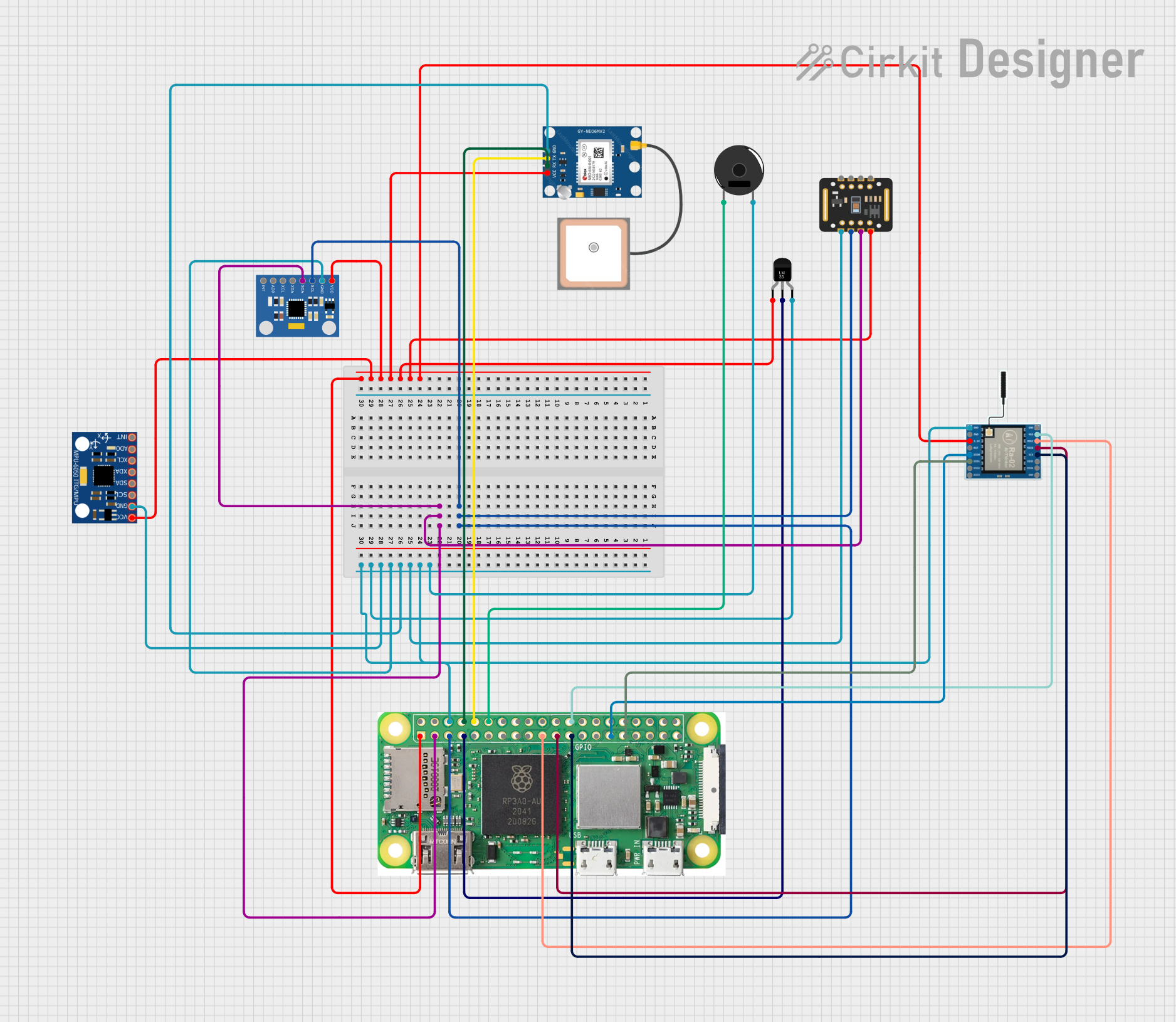
Explore Projects Built with Orange Pi Zero 3
Common Applications and Use Cases
- IoT Projects: Ideal for creating smart home devices, sensors, and other IoT applications.
- Media Centers: Can be used to build a compact and efficient media center for streaming and local media playback.
- Educational Purposes: Great for learning about computer science, electronics, and programming.
- Networked Devices: Suitable for creating networked devices such as routers, NAS, and more.
Technical Specifications
Key Technical Details
| Specification | Details |
|---|---|
| Processor | Allwinner H618 Quad-Core ARM Cortex-A53 |
| RAM | 1GB DDR3 |
| Storage | MicroSD card slot, up to 128GB |
| Connectivity | Wi-Fi 802.11 b/g/n, Bluetooth 5.0, Ethernet |
| USB Ports | 1 x USB 2.0, 1 x USB OTG |
| GPIO | 26-pin header |
| Power Supply | 5V/2A via Micro USB |
| Operating System | Linux, Android |
| Dimensions | 48mm x 46mm |
Pin Configuration and Descriptions
GPIO Header Pinout
| Pin Number | Name | Description |
|---|---|---|
| 1 | 3.3V | 3.3V Power |
| 2 | 5V | 5V Power |
| 3 | GPIO2 | General Purpose I/O |
| 4 | 5V | 5V Power |
| 5 | GPIO3 | General Purpose I/O |
| 6 | GND | Ground |
| 7 | GPIO4 | General Purpose I/O |
| 8 | UART1_TX | UART Transmit |
| 9 | GND | Ground |
| 10 | UART1_RX | UART Receive |
| 11 | GPIO17 | General Purpose I/O |
| 12 | GPIO18 | General Purpose I/O |
| 13 | GPIO27 | General Purpose I/O |
| 14 | GND | Ground |
| 15 | GPIO22 | General Purpose I/O |
| 16 | GPIO23 | General Purpose I/O |
| 17 | 3.3V | 3.3V Power |
| 18 | GPIO24 | General Purpose I/O |
| 19 | SPI_MOSI | SPI Master Out Slave In |
| 20 | GND | Ground |
| 21 | SPI_MISO | SPI Master In Slave Out |
| 22 | GPIO25 | General Purpose I/O |
| 23 | SPI_CLK | SPI Clock |
| 24 | SPI_CS0 | SPI Chip Select 0 |
| 25 | GND | Ground |
| 26 | SPI_CS1 | SPI Chip Select 1 |
Usage Instructions
How to Use the Orange Pi Zero 3 in a Circuit
- Power Supply: Connect a 5V/2A power supply to the Micro USB port.
- Storage: Insert a MicroSD card with a compatible operating system (e.g., Linux, Android).
- Network: Connect to a network using Wi-Fi, Bluetooth, or Ethernet.
- GPIO: Use the 26-pin header for connecting sensors, actuators, and other peripherals.
Important Considerations and Best Practices
- Power Supply: Ensure a stable 5V/2A power supply to avoid power-related issues.
- Cooling: Consider adding a heat sink or fan for better thermal management, especially under heavy load.
- OS Compatibility: Use a compatible operating system image to ensure proper functionality.
- Static Precautions: Handle the board with care to avoid static discharge damage.
Troubleshooting and FAQs
Common Issues and Solutions
Board Not Powering On:
- Solution: Check the power supply and ensure it provides 5V/2A. Verify the Micro USB connection.
No Display Output:
- Solution: Ensure the operating system image is correctly written to the MicroSD card. Check the HDMI connection if using an HDMI adapter.
Wi-Fi/Bluetooth Not Working:
- Solution: Verify that the correct drivers are installed. Check the network settings and ensure the antennas are properly connected.
Overheating:
- Solution: Add a heat sink or fan to improve cooling. Ensure proper ventilation around the board.
FAQs
Q: Can I use a different power supply? A: It is recommended to use a 5V/2A power supply to ensure stable operation. Using a different power supply may cause instability.
Q: What operating systems are supported? A: The Orange Pi Zero 3 supports various Linux distributions and Android.
Q: How do I connect to Wi-Fi? A: Use the network settings in your operating system to connect to a Wi-Fi network. Ensure the Wi-Fi drivers are installed.
Q: Can I expand the storage? A: Yes, you can use a MicroSD card up to 128GB for storage expansion.
Example Code for Arduino UNO Integration
While the Orange Pi Zero 3 is a standalone SBC, it can be used in conjunction with an Arduino UNO for various projects. Below is an example of how to communicate between the Orange Pi Zero 3 and an Arduino UNO using UART.
Arduino UNO Code
void setup() {
  Serial.begin(9600); // Initialize serial communication at 9600 baud
}

void loop() {
  if (Serial.available() > 0) {
    String data = Serial.readString(); // Read data from Orange Pi Zero 3
    Serial.println("Received: " + data); // Print received data
  }
  delay(1000); // Wait for 1 second
}
Python Code for Orange Pi Zero 3
import serial
import time
Initialize serial communication with Arduino UNO
ser = serial.Serial('/dev/ttyS1', 9600, timeout=1)
while True: ser.write(b'Hello from Orange Pi Zero 3\n') # Send data to Arduino UNO time.sleep(1) # Wait for 1 second
This example demonstrates basic UART communication between the Orange Pi Zero 3 and an Arduino UNO. Ensure the UART pins are correctly connected between the two devices.

---

This documentation provides a comprehensive overview of the Orange Pi Zero 3, including its technical specifications, usage instructions, troubleshooting tips, and example code for integration with an Arduino UNO. Whether you are a beginner or an experienced user, this guide aims to help you make the most of your Orange Pi Zero 3.