Cirkit Designer
Your all-in-one circuit design IDE
Home /
Component Documentation
How to Use Receiver RF Module: Examples, Pinouts, and Specs
Introduction
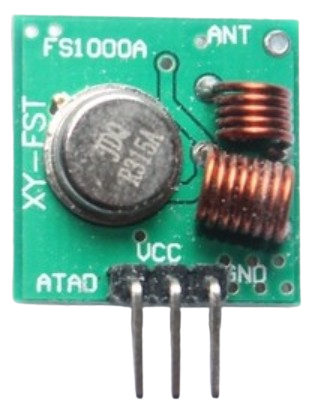
A Receiver RF Module is an electronic device designed to receive radio frequency (RF) signals and convert them into a form that can be understood and processed by electronic circuits. These modules are essential components in wireless communication systems, including remote controls, telemetry, and RFID systems. They are commonly used in conjunction with a transmitter RF module that sends the signals which the receiver module captures and processes.
Explore Projects Built with Receiver RF Module
Arduino UNO with 433MHz RF Module for Wireless Communication

This circuit consists of an Arduino UNO connected to an RXN433MHz radio frequency module. The Arduino provides 5V power and ground to the RF module and is configured to communicate with it via digital pin D11. Additionally, a multimeter is connected with alligator clip cables to measure the voltage supplied to the RF module.
ESP32-Based RF Communication System with 433 MHz Modules

This circuit comprises an ESP32 microcontroller connected to a 433 MHz RF transmitter and receiver pair. The ESP32 is programmed to receive and decode RF signals through the receiver module, as well as send RF signals via the transmitter module. Additionally, the ESP32 can communicate with a Bluetooth device to exchange commands and data, and it uses an LED for status indication.
433 MHz RF Transmitter and Receiver with Arduino Uno for Wireless LED Control

This circuit consists of two Arduino Uno R3 microcontrollers communicating wirelessly using 433 MHz RF modules. One Arduino is connected to an RF transmitter to send data, while the other Arduino is connected to an RF receiver to receive data and control an LED based on the received signal.
433 MHz RF Transmitter and Receiver with Arduino UNO for Wireless Communication

This circuit consists of two Arduino UNO microcontrollers, each connected to an RF 433 MHz Transmitter and a 433 MHz RF Receiver Module. The setup allows for wireless communication between the two Arduinos, enabling them to send and receive data over a 433 MHz RF link.
Explore Projects Built with Receiver RF Module
Arduino UNO with 433MHz RF Module for Wireless Communication
This circuit consists of an Arduino UNO connected to an RXN433MHz radio frequency module. The Arduino provides 5V power and ground to the RF module and is configured to communicate with it via digital pin D11. Additionally, a multimeter is connected with alligator clip cables to measure the voltage supplied to the RF module.
ESP32-Based RF Communication System with 433 MHz Modules
This circuit comprises an ESP32 microcontroller connected to a 433 MHz RF transmitter and receiver pair. The ESP32 is programmed to receive and decode RF signals through the receiver module, as well as send RF signals via the transmitter module. Additionally, the ESP32 can communicate with a Bluetooth device to exchange commands and data, and it uses an LED for status indication.
433 MHz RF Transmitter and Receiver with Arduino Uno for Wireless LED Control
This circuit consists of two Arduino Uno R3 microcontrollers communicating wirelessly using 433 MHz RF modules. One Arduino is connected to an RF transmitter to send data, while the other Arduino is connected to an RF receiver to receive data and control an LED based on the received signal.
433 MHz RF Transmitter and Receiver with Arduino UNO for Wireless Communication
This circuit consists of two Arduino UNO microcontrollers, each connected to an RF 433 MHz Transmitter and a 433 MHz RF Receiver Module. The setup allows for wireless communication between the two Arduinos, enabling them to send and receive data over a 433 MHz RF link.
Common Applications and Use Cases
- Remote control systems for TVs, garage doors, and drones
- Wireless data transmission for telemetry
- RFID readers for identification and tracking
- Amateur radio equipment
- Wireless sensor networks
Technical Specifications
Key Technical Details
- Operating Frequency: Typically ranges from 433 MHz, 868 MHz, or 915 MHz, depending on the specific model and region.
- Sensitivity: The minimum signal strength the receiver can detect, often measured in dBm.
- Voltage Supply Range: Commonly 3.3V to 5V for compatibility with various logic levels.
- Current Consumption: Varies with the operating mode, typically in the range of a few mA to tens of mA.
- Modulation Techniques Supported: ASK (Amplitude Shift Keying), FSK (Frequency Shift Keying), etc.
Pin Configuration and Descriptions
| Pin Number | Name | Description |
|---|---|---|
| 1 | VCC | Power supply input, typically 3.3V to 5V |
| 2 | GND | Ground connection |
| 3 | DATA | Data output pin, outputs the demodulated data |
| 4 | ANT | Antenna connection, for receiving RF signals |
| 5 | NC | No Connection (if applicable) |
Usage Instructions
How to Use the Component in a Circuit
- Power Supply: Connect the VCC pin to a power source within the specified voltage range and the GND pin to the ground of the power supply.
- Antenna: Attach an appropriate antenna to the ANT pin to ensure proper signal reception.
- Data Output: Connect the DATA pin to a digital input pin on a microcontroller, such as an Arduino, to read the demodulated data.
Important Considerations and Best Practices
- Antenna Design: The length and type of the antenna are crucial for optimal performance. For a 433 MHz module, a quarter-wave monopole antenna is approximately 17 cm long.
- Power Supply Filtering: Use capacitors to filter noise from the power supply, ensuring stable operation.
- Placement: Keep the receiver away from metal objects and noise sources for better reception.
- Data Decoding: Implement proper decoding algorithms in the microcontroller to interpret the received signals correctly.
Example Code for Arduino UNO
// Example code for interfacing a Receiver RF Module with an Arduino UNO
int dataPin = 2; // Connect the DATA pin of the RF receiver to digital pin 2

void setup() {
  pinMode(dataPin, INPUT); // Set the data pin as an input
  Serial.begin(9600); // Start serial communication at 9600 baud rate
}

void loop() {
  int dataValue = digitalRead(dataPin); // Read the data received by the RF module
  Serial.println(dataValue); // Print the data to the Serial Monitor
  delay(100); // Wait for 100 milliseconds before reading the data again
}
Troubleshooting and FAQs
Common Issues Users Might Face
- No Signal Reception: Ensure the antenna is properly connected and the module is powered correctly.
- Intermittent Signal: Check for sources of interference and consider using a different frequency or antenna.
- Weak Signal: Move the receiver closer to the transmitter or use a higher gain antenna.
Solutions and Tips for Troubleshooting
- Power Supply Issues: Verify the voltage levels with a multimeter and ensure stable power supply.
- Antenna Issues: Experiment with different antenna lengths and types for better reception.
- Data Decoding: Make sure the decoding algorithm matches the transmitter's encoding method.
FAQs
Q: Can I use a 5V power supply with the receiver RF module?
- A: Yes, if the module's specifications state that it can handle a 5V supply.
Q: How can I increase the range of my receiver RF module?
- A: Use a higher gain antenna, ensure there is a clear line of sight, or increase the transmitter's power, if possible.
Q: What should I do if there's a lot of noise in the received signal?
- A: Use filtering techniques, both in hardware (capacitors, inductors) and software (signal processing algorithms) to reduce noise.