How to Use mini v6.7: Examples, Pinouts, and Specs
Introduction
The Mini v6.7 is a compact and versatile microcontroller board designed for a wide range of electronic projects. It features multiple input/output (I/O) pins, built-in connectivity options, and compatibility with various programming environments, making it an excellent choice for hobbyists, students, and professionals alike. Its small form factor and robust functionality allow it to be seamlessly integrated into projects requiring precise control, automation, or data processing.
Explore Projects Built with mini v6.7
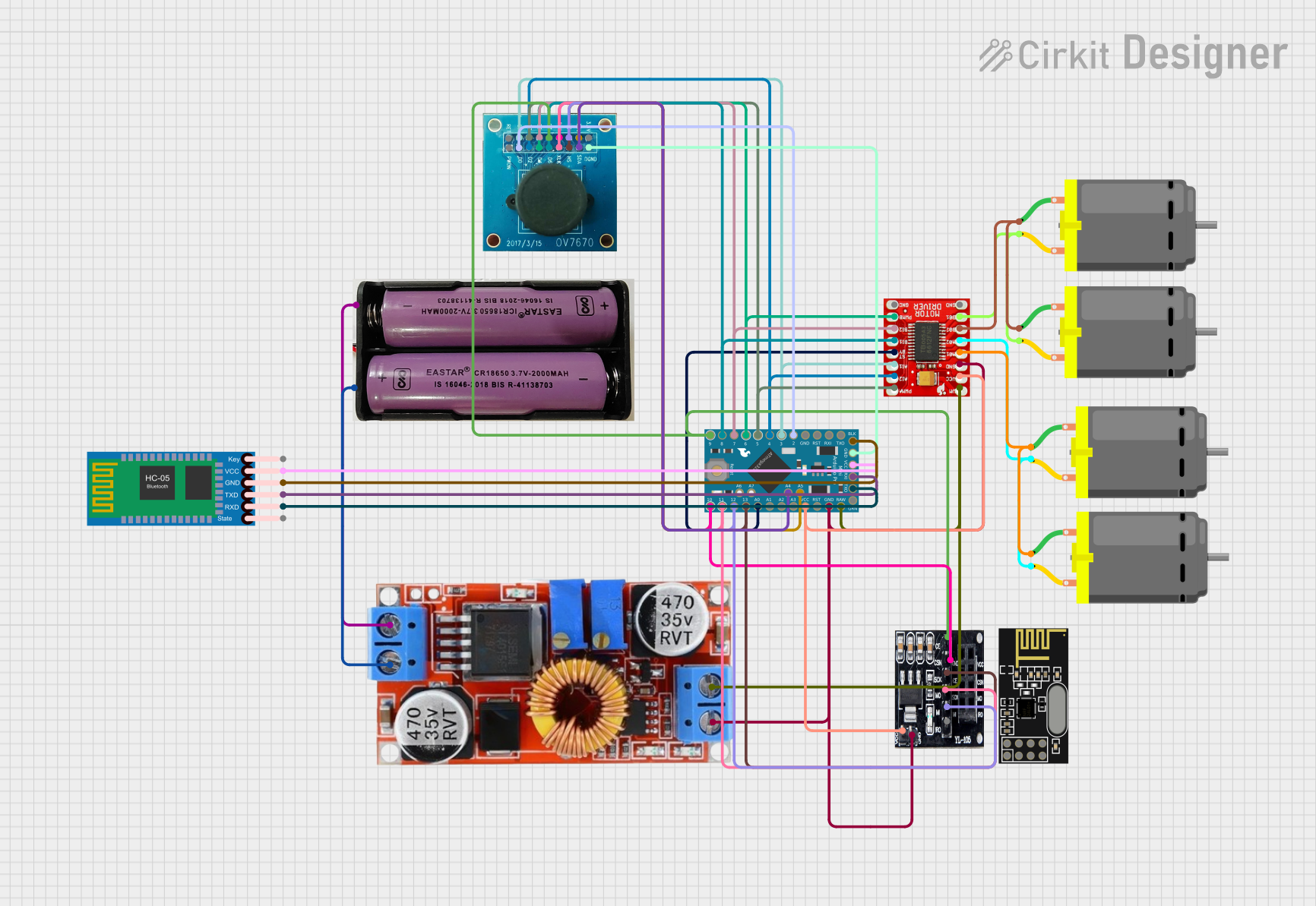

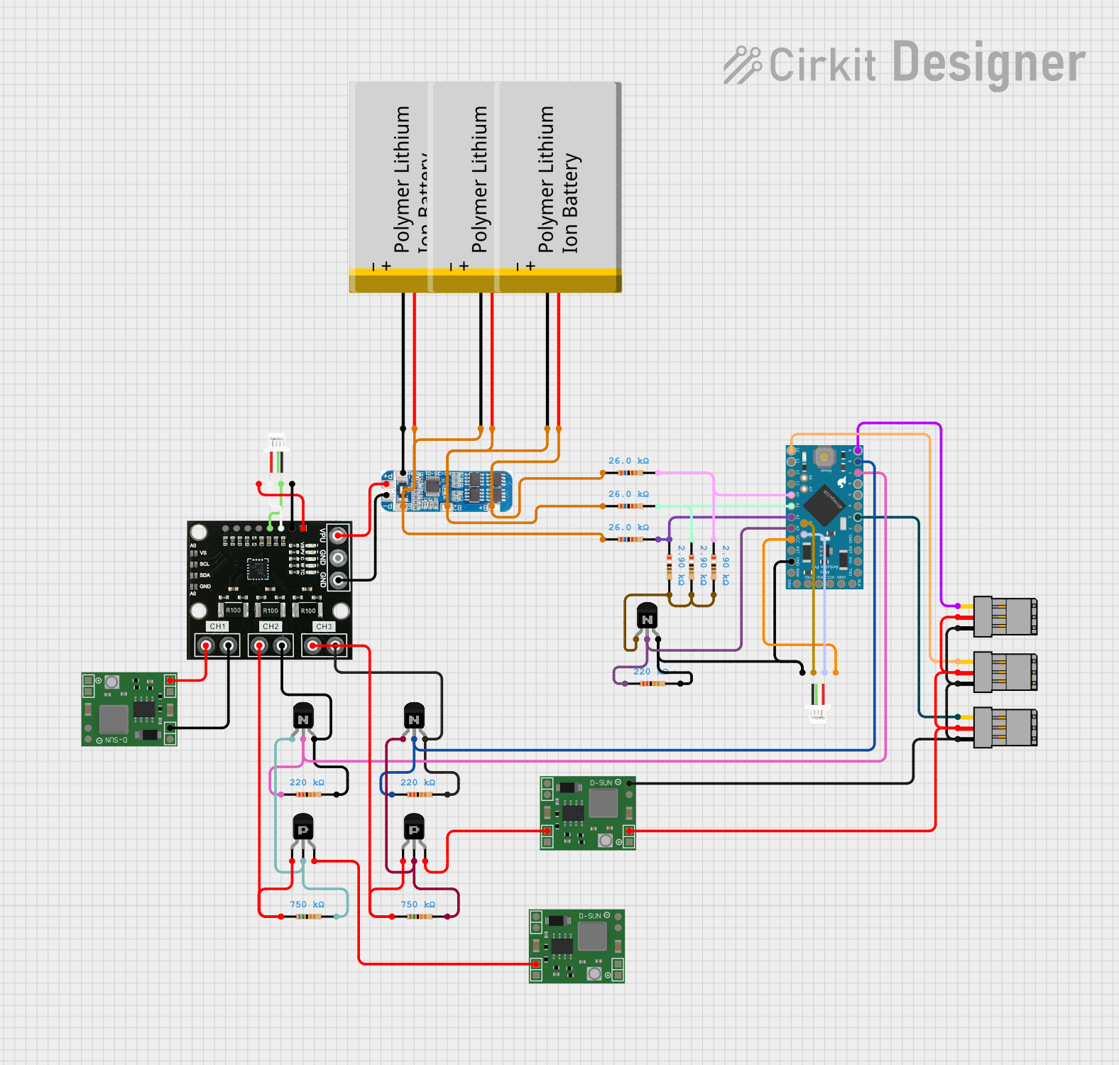
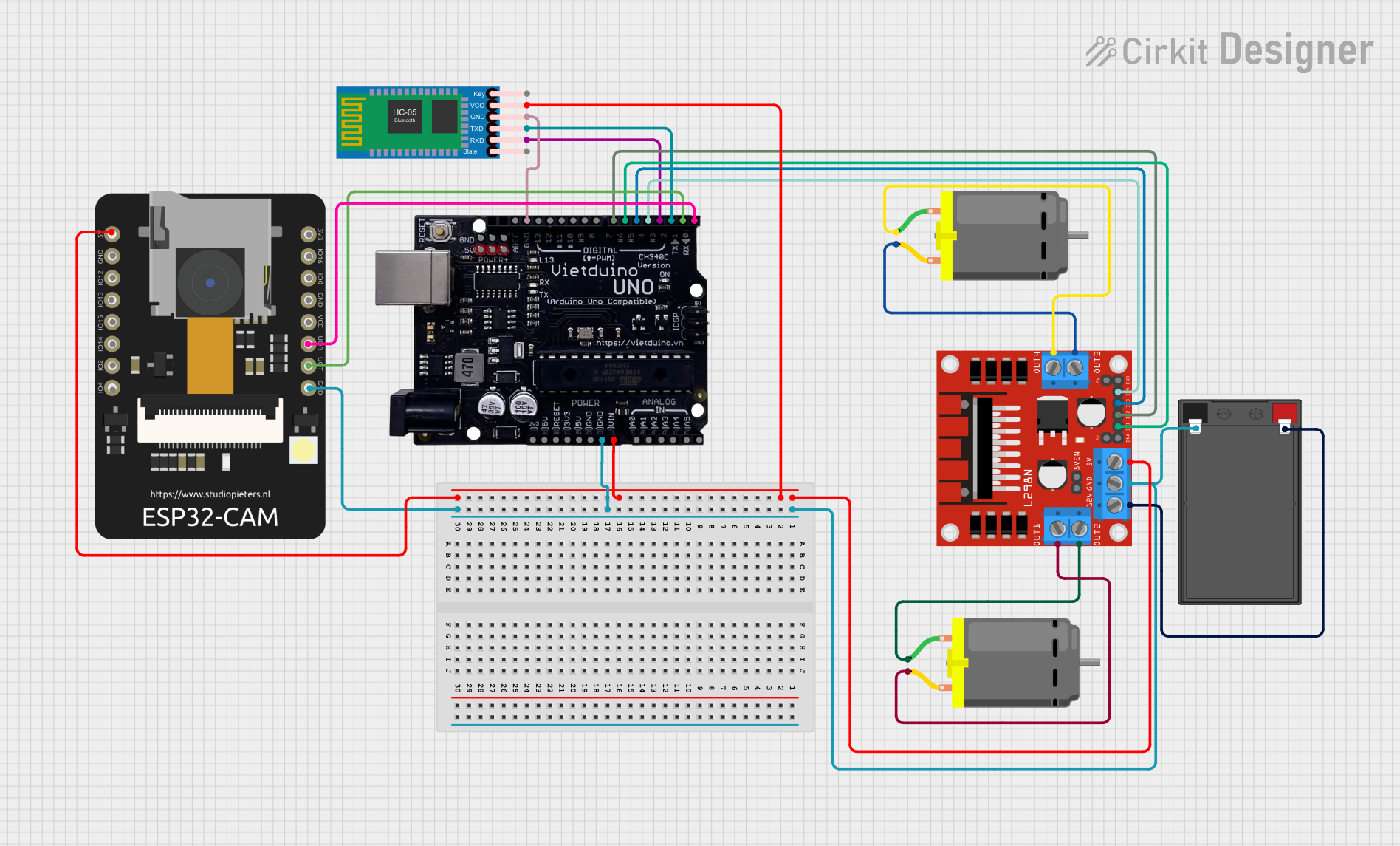
Explore Projects Built with mini v6.7
Common Applications
- Home automation systems
- Robotics and motor control
- IoT (Internet of Things) devices
- Sensor data acquisition and processing
- Wearable electronics
- Educational and prototyping projects
Technical Specifications
The Mini v6.7 is equipped with the following technical features:
| Specification | Details |
|---|---|
| Microcontroller | ARM Cortex-M4, 32-bit, 120 MHz |
| Flash Memory | 256 KB |
| SRAM | 64 KB |
| Operating Voltage | 3.3V |
| Input Voltage (VIN) | 5V - 12V |
| Digital I/O Pins | 14 (6 PWM capable) |
| Analog Input Pins | 6 |
| Communication Interfaces | UART, I2C, SPI |
| Connectivity | Built-in Wi-Fi and Bluetooth 4.2 |
| USB Interface | Micro-USB for programming and power |
| Dimensions | 35 mm x 25 mm |
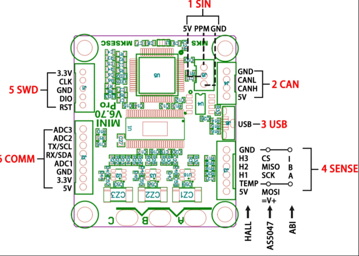
Pin Configuration and Descriptions
The Mini v6.7 features a total of 20 pins, including power, digital, and analog pins. Below is the pin configuration:
| Pin | Type | Description |
|---|---|---|
| VIN | Power Input | External power input (5V - 12V) |
| GND | Power Ground | Ground connection |
| 3.3V | Power Output | Regulated 3.3V output |
| D0-D13 | Digital I/O | General-purpose digital pins (D3, D5, D6, D9, D10, D11 support PWM) |
| A0-A5 | Analog Input | Analog input pins (10-bit resolution) |
| TX | UART TX | Transmit pin for serial communication |
| RX | UART RX | Receive pin for serial communication |
| SCL | I2C Clock | Clock line for I2C communication |
| SDA | I2C Data | Data line for I2C communication |
| MOSI | SPI Data Out | Master Out Slave In pin for SPI communication |
| MISO | SPI Data In | Master In Slave Out pin for SPI communication |
| SCK | SPI Clock | Clock pin for SPI communication |
Usage Instructions
Using the Mini v6.7 in a Circuit
Powering the Board:
- Connect the VIN pin to an external power source (5V - 12V) or use the Micro-USB port for power and programming.
- Ensure the GND pin is connected to the ground of your circuit.
Connecting I/O Devices:
- Use the digital pins (D0-D13) for controlling LEDs, relays, or other digital devices.
- Use the analog pins (A0-A5) for reading sensor data or other analog signals.
Programming the Board:
- Connect the Mini v6.7 to your computer via the Micro-USB cable.
- Use a compatible IDE (e.g., Arduino IDE, PlatformIO) to write and upload code.
Communication Interfaces:
- Use UART (TX/RX) for serial communication with other devices.
- Use I2C (SCL/SDA) or SPI (MOSI/MISO/SCK) for interfacing with sensors, displays, or other peripherals.
Important Considerations
- Ensure the input voltage does not exceed the specified range (5V - 12V) to avoid damaging the board.
- Use appropriate pull-up resistors for I2C communication if required by your peripherals.
- Avoid drawing more current than the board's maximum output capacity (3.3V pin).
Example: Blinking an LED with Arduino UNO
Below is an example of how to use the Mini v6.7 to blink an LED connected to pin D13:
// This example demonstrates how to blink an LED connected to pin D13
// on the Mini v6.7 microcontroller board.

void setup() {
  pinMode(13, OUTPUT); // Set pin D13 as an output pin
}

void loop() {
  digitalWrite(13, HIGH); // Turn the LED on
  delay(1000);            // Wait for 1 second
  digitalWrite(13, LOW);  // Turn the LED off
  delay(1000);            // Wait for 1 second
}
Troubleshooting and FAQs
Common Issues
The board is not powering on:
- Ensure the power source is within the specified voltage range (5V - 12V).
- Check the Micro-USB cable and connection.
Unable to upload code:
- Verify that the correct board and port are selected in the IDE.
- Ensure the necessary drivers for the Mini v6.7 are installed on your computer.
Wi-Fi or Bluetooth not working:
- Check the connectivity settings in your code.
- Ensure the board is within range of the Wi-Fi network or Bluetooth device.
FAQs
Q: Can the Mini v6.7 operate at 5V logic levels?
A: No, the Mini v6.7 operates at 3.3V logic levels. Use a level shifter if interfacing with 5V devices.
Q: What is the maximum current output of the 3.3V pin?
A: The 3.3V pin can supply up to 50 mA of current.
Q: Is the Mini v6.7 compatible with Arduino libraries?
A: Yes, the Mini v6.7 is compatible with most Arduino libraries, making it easy to integrate into existing projects.
Q: Can I use the Mini v6.7 for battery-powered projects?
A: Yes, you can power the board using a battery within the specified voltage range (5V - 12V).