Cirkit Designer Logo
Cirkit Designer
Your all-in-one circuit design IDE
Home / 
Component Documentation

How to Use Magnetic Key Card Switch: Examples, Pinouts, and Specs

Image of Magnetic Key Card Switch
Cirkit Designer LogoDesign with Magnetic Key Card Switch in Cirkit Designer

Introduction

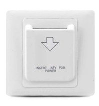
The Magnetic Key Card Switch is a device that utilizes a magnetic strip on a card to control the opening and closing of an electrical switch. It is widely used in access control systems, such as hotel room power management, secure entry systems, and automated locking mechanisms. The switch operates by detecting the unique magnetic pattern encoded on the card, ensuring secure and reliable operation.

Explore Projects Built with Magnetic Key Card Switch

Use Cirkit Designer to design, explore, and prototype these projects online. Some projects support real-time simulation. Click "Open Project" to start designing instantly!
Arduino UNO RFID Door Lock System with Keypad and Buzzer
Image of Copy of Door Lock System (1): A project utilizing Magnetic Key Card Switch in a practical application
This circuit is an RFID-based door lock system controlled by an Arduino UNO. It uses an RFID reader and a membrane keypad for access control, with visual and auditory feedback provided by LEDs and a buzzer. The system includes a relay to control a magnetic lock, and features for registering and deleting RFID cards, as well as handling failed access attempts.
Cirkit Designer LogoOpen Project in Cirkit Designer
Arduino UNO RFID Door Lock System with Relay and Buzzer Notification
Image of Door Lock System: A project utilizing Magnetic Key Card Switch in a practical application
This circuit is designed as an RFID-based access control system that operates a magnetic door lock. The Arduino UNO reads RFID tags using the RFID-RC522 module and controls a magnetic lock via a 12V relay, indicating access status with red and green LEDs and a buzzer. The system grants or denies access based on the RFID tag presented, unlocking the door for authorized tags and sounding an alert for unauthorized attempts.
Cirkit Designer LogoOpen Project in Cirkit Designer
NFC-Enabled Access Control System with Time Logging
Image of doorlock: A project utilizing Magnetic Key Card Switch in a practical application
This circuit is designed for access control with time tracking capabilities. It features an NFC/RFID reader for authentication, an RTC module (DS3231) for real-time clock functionality, and an OLED display for user interaction. A 12V relay controls a magnetic lock, which is activated upon successful NFC/RFID authentication, and a button switch is likely used for manual operation or input. The T8_S3 microcontroller serves as the central processing unit, interfacing with the NFC/RFID reader, RTC, OLED, and relay to manage the access control logic.
Cirkit Designer LogoOpen Project in Cirkit Designer
NFC-Enabled Access Control System with Real-Time Clock and OLED Display
Image of doorlock: A project utilizing Magnetic Key Card Switch in a practical application
This circuit is designed as an access control system with time-tracking capabilities. It uses an NFC/RFID reader for authentication, a real-time clock for time-stamping events, and an OLED display for user interface, all controlled by a T8_S3 microcontroller. A relay module actuates a magnetic lock, and a button switch provides additional user input, with a switching power supply delivering the necessary voltages.
Cirkit Designer LogoOpen Project in Cirkit Designer

Explore Projects Built with Magnetic Key Card Switch

Use Cirkit Designer to design, explore, and prototype these projects online. Some projects support real-time simulation. Click "Open Project" to start designing instantly!
Image of Copy of Door Lock System (1): A project utilizing Magnetic Key Card Switch in a practical application
Arduino UNO RFID Door Lock System with Keypad and Buzzer
This circuit is an RFID-based door lock system controlled by an Arduino UNO. It uses an RFID reader and a membrane keypad for access control, with visual and auditory feedback provided by LEDs and a buzzer. The system includes a relay to control a magnetic lock, and features for registering and deleting RFID cards, as well as handling failed access attempts.
Cirkit Designer LogoOpen Project in Cirkit Designer
Image of Door Lock System: A project utilizing Magnetic Key Card Switch in a practical application
Arduino UNO RFID Door Lock System with Relay and Buzzer Notification
This circuit is designed as an RFID-based access control system that operates a magnetic door lock. The Arduino UNO reads RFID tags using the RFID-RC522 module and controls a magnetic lock via a 12V relay, indicating access status with red and green LEDs and a buzzer. The system grants or denies access based on the RFID tag presented, unlocking the door for authorized tags and sounding an alert for unauthorized attempts.
Cirkit Designer LogoOpen Project in Cirkit Designer
Image of doorlock: A project utilizing Magnetic Key Card Switch in a practical application
NFC-Enabled Access Control System with Time Logging
This circuit is designed for access control with time tracking capabilities. It features an NFC/RFID reader for authentication, an RTC module (DS3231) for real-time clock functionality, and an OLED display for user interaction. A 12V relay controls a magnetic lock, which is activated upon successful NFC/RFID authentication, and a button switch is likely used for manual operation or input. The T8_S3 microcontroller serves as the central processing unit, interfacing with the NFC/RFID reader, RTC, OLED, and relay to manage the access control logic.
Cirkit Designer LogoOpen Project in Cirkit Designer
Image of doorlock: A project utilizing Magnetic Key Card Switch in a practical application
NFC-Enabled Access Control System with Real-Time Clock and OLED Display
This circuit is designed as an access control system with time-tracking capabilities. It uses an NFC/RFID reader for authentication, a real-time clock for time-stamping events, and an OLED display for user interface, all controlled by a T8_S3 microcontroller. A relay module actuates a magnetic lock, and a button switch provides additional user input, with a switching power supply delivering the necessary voltages.
Cirkit Designer LogoOpen Project in Cirkit Designer

Common Applications:

  • Hotel room power control (activating room power when the card is inserted)
  • Secure access control for doors and gates
  • Industrial equipment activation
  • Time-based access systems in offices or restricted areas

Technical Specifications

Key Technical Details:

  • Operating Voltage: 5V to 12V DC
  • Current Consumption: 50mA (typical)
  • Switch Type: Normally Open (NO) or Normally Closed (NC), depending on configuration
  • Card Type: Magnetic stripe card (ISO/IEC 7810 standard)
  • Detection Method: Magnetic stripe pattern recognition
  • Output Type: Digital signal (High/Low)
  • Operating Temperature: -10°C to 50°C
  • Dimensions: 86mm x 86mm x 35mm (typical wall-mounted size)

Pin Configuration and Descriptions:

Pin Name Description Notes
VCC Power supply input (5V to 12V DC) Connect to the positive terminal of the power source.
GND Ground Connect to the ground of the circuit.
OUT Digital output signal Outputs HIGH when the correct card is detected.
LED+ Positive terminal for status LED Optional connection for an external LED.
LED- Negative terminal for status LED Connect to ground for LED operation.

Usage Instructions

How to Use the Magnetic Key Card Switch in a Circuit:

  1. Power Connection:

    • Connect the VCC pin to a 5V or 12V DC power source.
    • Connect the GND pin to the ground of the power source.
  2. Output Signal:

    • The OUT pin provides a digital signal. It outputs a HIGH signal when the correct magnetic card is detected and a LOW signal otherwise.
    • This output can be connected to a microcontroller (e.g., Arduino) or a relay module to control other devices.
  3. Optional LED Indicator:

    • Connect an external LED to the LED+ and LED- pins to visually indicate the card detection status.
  4. Card Usage:

    • Swipe or insert the magnetic card into the switch. Ensure the card's magnetic stripe is aligned with the reader's sensor.

Important Considerations:

  • Ensure the magnetic card is clean and undamaged for reliable operation.
  • Avoid placing the switch near strong magnetic fields, as they may interfere with detection.
  • Use a regulated power supply to prevent voltage fluctuations that could damage the switch.

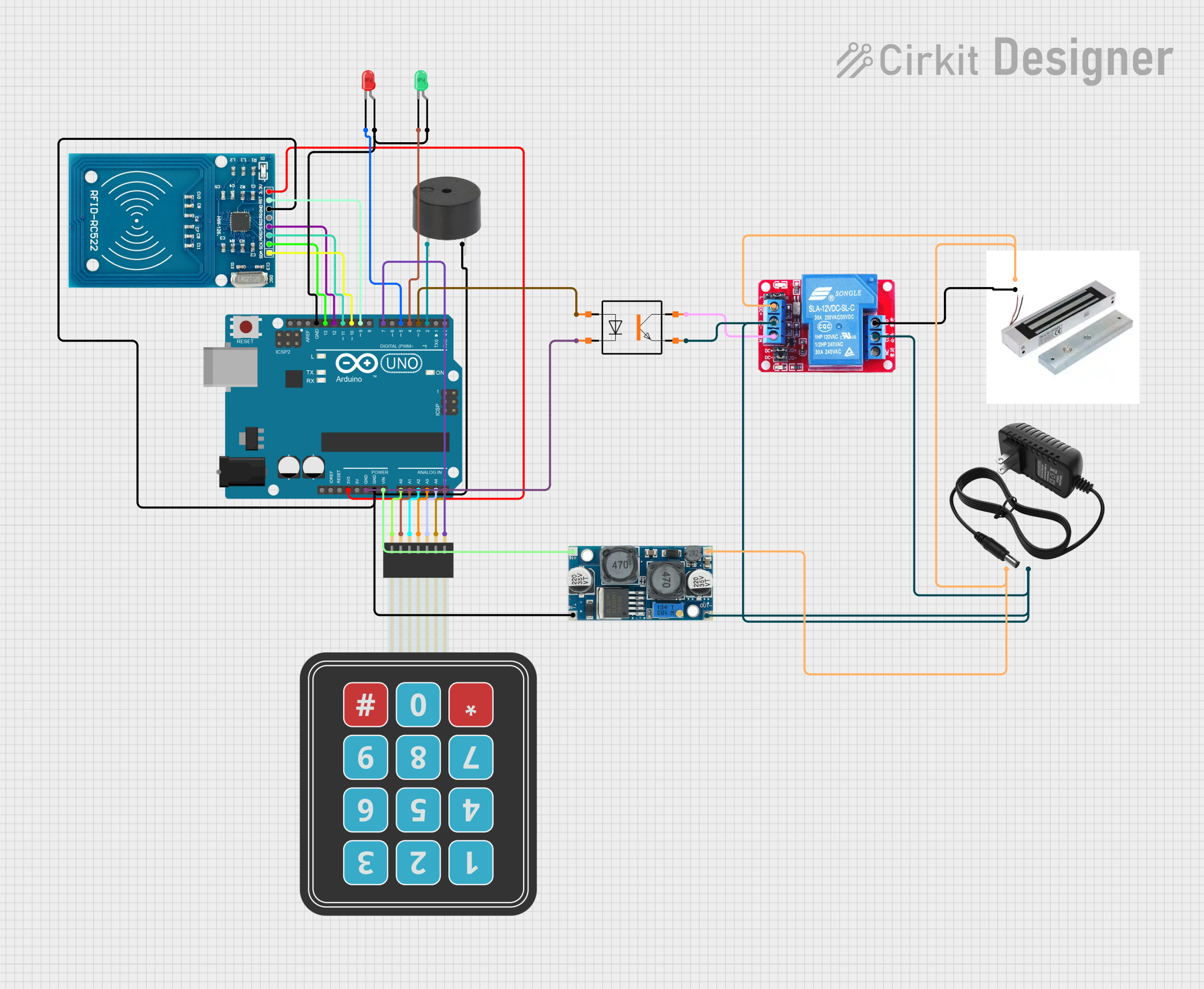
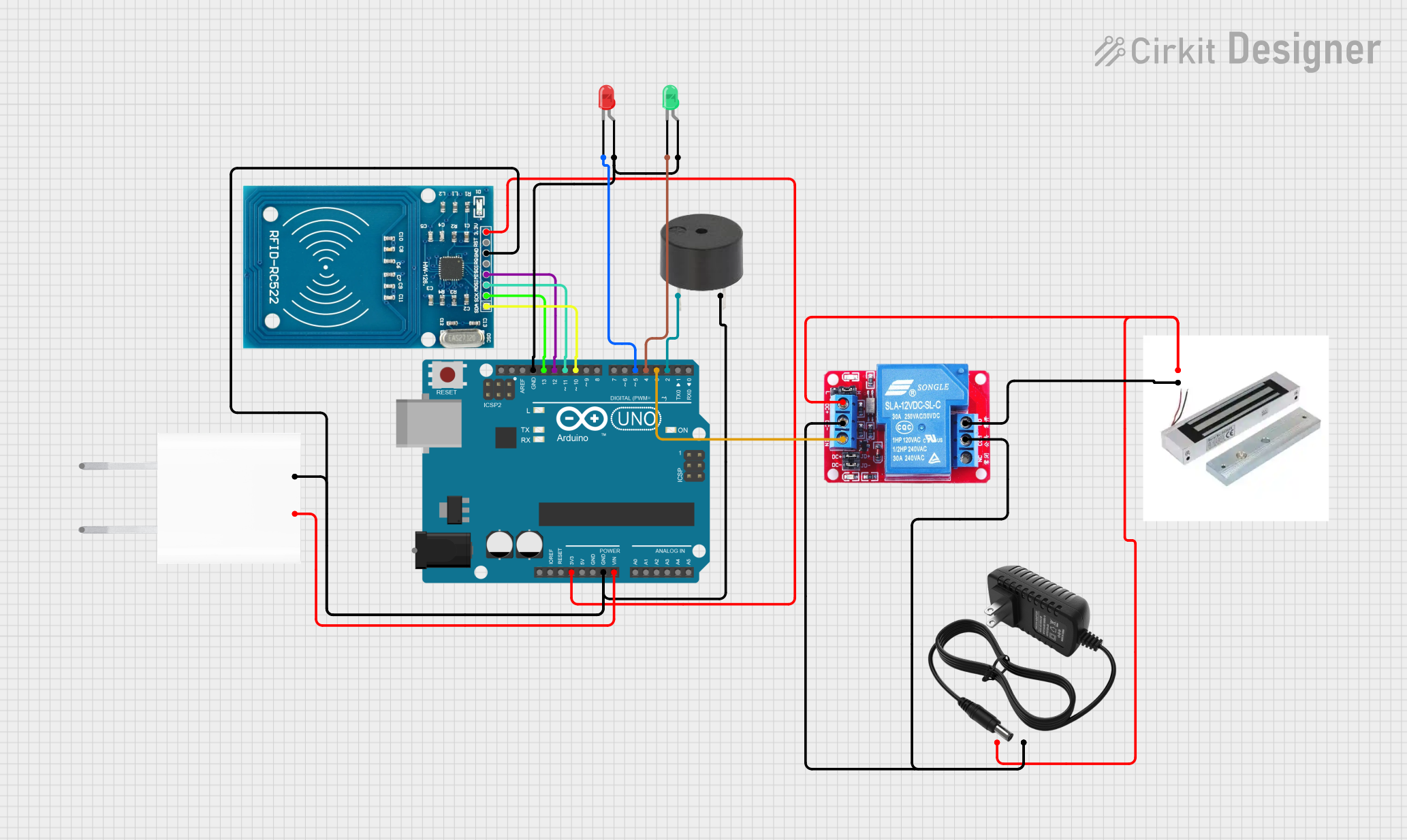
Example: Connecting to an Arduino UNO

Below is an example of how to connect the Magnetic Key Card Switch to an Arduino UNO and read the output signal.

Circuit Connections:

  • VCC → 5V pin on Arduino
  • GND → GND pin on Arduino
  • OUT → Digital pin 2 on Arduino

Arduino Code:

// Magnetic Key Card Switch Example
// This code reads the output signal from the switch and turns on an LED
// when the correct card is detected.

const int switchPin = 2;  // Pin connected to the OUT pin of the switch
const int ledPin = 13;    // Built-in LED on Arduino

void setup() {
  pinMode(switchPin, INPUT);  // Set the switch pin as input
  pinMode(ledPin, OUTPUT);    // Set the LED pin as output
  Serial.begin(9600);         // Initialize serial communication
}

void loop() {
  int switchState = digitalRead(switchPin);  // Read the switch state

  if (switchState == HIGH) {
    // If the correct card is detected, turn on the LED
    digitalWrite(ledPin, HIGH);
    Serial.println("Card detected!");
  } else {
    // If no card or incorrect card, turn off the LED
    digitalWrite(ledPin, LOW);
    Serial.println("No card detected.");
  }

  delay(100);  // Small delay for stability
}

Troubleshooting and FAQs

Common Issues:

  1. The switch does not detect the card:

    • Ensure the card's magnetic stripe is clean and undamaged.
    • Verify that the card is being swiped or inserted in the correct orientation.
    • Check the power supply voltage and connections.
  2. Output signal is unstable:

    • Use a regulated power supply to avoid voltage fluctuations.
    • Ensure the switch is not exposed to strong electromagnetic interference.
  3. LED does not light up:

    • Verify the LED connections to the LED+ and LED- pins.
    • Check if the correct card is being used.

FAQs:

  • Can I use any magnetic card with this switch? No, the switch is designed to detect specific magnetic stripe patterns. Ensure the card matches the system's configuration.

  • What happens if the card is swiped too quickly? The switch may fail to read the magnetic stripe. Swipe the card at a moderate and consistent speed.

  • Can this switch be used outdoors? The switch is not weatherproof. Use it indoors or in a protected enclosure for outdoor applications.

  • Is it compatible with RFID cards? No, this switch is designed for magnetic stripe cards only. Use an RFID reader for RFID cards.