
How to Use EBYTE E28-2G4M27SX : Examples, Pinouts, and Specs
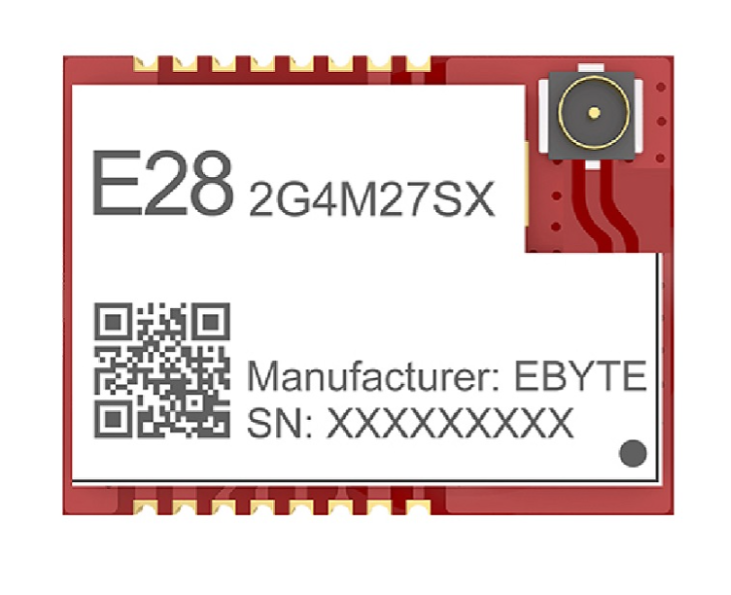
 Design with EBYTE E28-2G4M27SX in Cirkit Designer
Introduction
The EBYTE E28-2G4M27SX is a low-power, long-range wireless transceiver module designed for IoT applications. Operating in the 2.4GHz frequency band, this module offers high sensitivity, robust communication capabilities, and excellent performance in environments requiring reliable wireless data transmission. Its compact design and versatile features make it ideal for applications such as smart homes, industrial automation, wireless sensor networks, and remote monitoring systems.
Explore Projects Built with EBYTE E28-2G4M27SX
 Open Project in Cirkit Designer
 Open Project in Cirkit Designer
 Open Project in Cirkit Designer
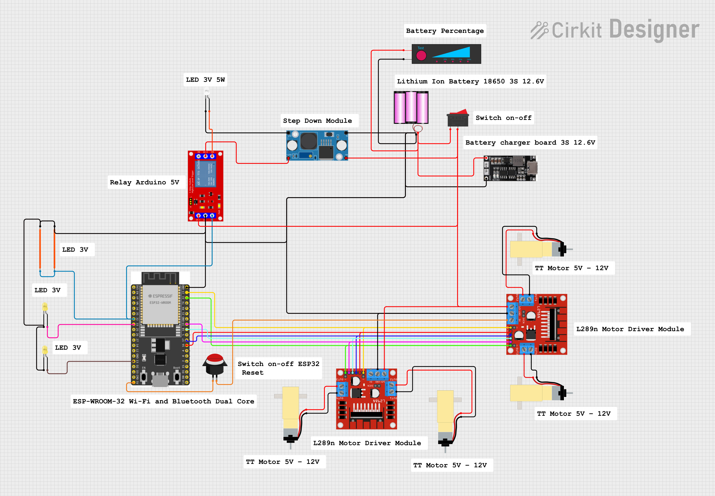
 Open Project in Cirkit Designer
Explore Projects Built with EBYTE E28-2G4M27SX

 Open Project in Cirkit Designer
 Open Project in Cirkit Designer
 Open Project in Cirkit Designer
 Open Project in Cirkit Designer
Common Applications
- Smart home devices (e.g., lighting, thermostats, and security systems)
- Industrial automation and control systems
- Wireless sensor networks
- Remote monitoring and telemetry
- Internet of Things (IoT) devices
Technical Specifications
The following table outlines the key technical specifications of the EBYTE E28-2G4M27SX module:
| Parameter | Value |
|---|---|
| Operating Frequency | 2.4GHz ISM band |
| Modulation Method | GFSK |
| Communication Distance | Up to 3,000 meters (line of sight) |
| Transmit Power | Up to 27dBm (adjustable) |
| Receiver Sensitivity | -102dBm |
| Operating Voltage | 1.8V to 3.6V |
| Operating Current | 15mA (transmit), 14mA (receive) |
| Sleep Current | < 1µA |
| Data Rate | 1.2kbps to 2Mbps |
| Operating Temperature | -40°C to +85°C |
| Dimensions | 16mm x 24mm x 2.2mm |
Pin Configuration and Descriptions
The E28-2G4M27SX module has 16 pins, each with specific functions. The table below provides a detailed description of each pin:
| Pin Number | Pin Name | Description |
|---|---|---|
| 1 | GND | Ground connection |
| 2 | VCC | Power supply input (1.8V to 3.6V) |
| 3 | TXD | UART transmit data |
| 4 | RXD | UART receive data |
| 5 | AUX | Status indicator (low during transmission/reception, high when idle) |
| 6 | SET | Configuration pin (used to enter setup mode) |
| 7 | NC | Not connected |
| 8 | NC | Not connected |
| 9 | NC | Not connected |
| 10 | NC | Not connected |
| 11 | NC | Not connected |
| 12 | NC | Not connected |
| 13 | NC | Not connected |
| 14 | NC | Not connected |
| 15 | NC | Not connected |
| 16 | ANT | Antenna interface (connect to external antenna for optimal performance) |
Usage Instructions
How to Use the E28-2G4M27SX in a Circuit
- Power Supply: Connect the VCC pin to a stable power source (1.8V to 3.6V) and the GND pin to ground.
- UART Communication: Use the TXD and RXD pins to interface with a microcontroller or other UART-compatible devices.
- Antenna Connection: Attach an external antenna to the ANT pin for optimal wireless performance.
- Configuration: Use the SET pin to enter configuration mode for setting parameters such as baud rate, frequency, and transmit power.
- Status Monitoring: Monitor the AUX pin to check the module's status (e.g., idle, transmitting, or receiving).
Important Considerations and Best Practices
- Power Supply: Ensure a clean and stable power supply to avoid communication errors.
- Antenna Placement: Position the antenna away from metal objects and other sources of interference for maximum range.
- Configuration: Use the manufacturer's configuration software or AT commands to set the module's parameters.
- UART Settings: Match the UART baud rate and other settings with the connected microcontroller or device.
- Heat Dissipation: Avoid placing the module in enclosed spaces without proper ventilation, especially during high-power transmission.
Example: Connecting to an Arduino UNO
The E28-2G4M27SX can be easily interfaced with an Arduino UNO using its UART pins. Below is an example circuit and code to send and receive data:
Circuit Connections
| E28-2G4M27SX Pin | Arduino UNO Pin |
|---|---|
| VCC | 3.3V |
| GND | GND |
| TXD | Pin 2 (RX) |
| RXD | Pin 3 (TX) |
| AUX | Not connected |
| SET | Not connected |
| ANT | External antenna |
Arduino Code
#include <SoftwareSerial.h>

// Define RX and TX pins for SoftwareSerial
SoftwareSerial E28Serial(2, 3); // RX = Pin 2, TX = Pin 3

void setup() {
  // Initialize serial communication with the module
  E28Serial.begin(9600); // Set baud rate to match the module's configuration
  Serial.begin(9600);    // For debugging via Serial Monitor

  Serial.println("E28-2G4M27SX Module Test");
}

void loop() {
  // Send data to the module
  E28Serial.println("Hello, EBYTE Module!");

  // Check if data is available from the module
  if (E28Serial.available()) {
    String receivedData = E28Serial.readString();
    Serial.print("Received: ");
    Serial.println(receivedData);
  }

  delay(1000); // Wait for 1 second before sending the next message
}
Troubleshooting and FAQs
Common Issues and Solutions
No Communication with the Module
- Cause: Incorrect UART connections or mismatched baud rate.
- Solution: Verify the TXD and RXD connections and ensure the baud rate matches the module's configuration.
Short Communication Range
- Cause: Poor antenna placement or interference.
- Solution: Ensure the antenna is properly connected and positioned away from interference sources.
Module Not Responding
- Cause: Incorrect power supply or damaged module.
- Solution: Check the power supply voltage and ensure it is within the specified range. Replace the module if necessary.
Configuration Issues
- Cause: Incorrect use of the SET pin or configuration software.
- Solution: Follow the manufacturer's instructions for entering configuration mode and setting parameters.
FAQs
Q: Can the module operate on 5V?
A: No, the module operates on a voltage range of 1.8V to 3.6V. Use a voltage regulator if your system operates at 5V.
Q: What is the maximum data rate supported?
A: The module supports data rates from 1.2kbps to 2Mbps.
Q: Is the module compatible with other 2.4GHz devices?
A: Yes, as long as the devices use the same communication protocol and frequency settings.
Q: How do I reset the module to factory settings?
A: Refer to the manufacturer's documentation for the specific AT command or procedure to reset the module.