How to Use RJ45 Female Breakout Board: Examples, Pinouts, and Specs
Introduction
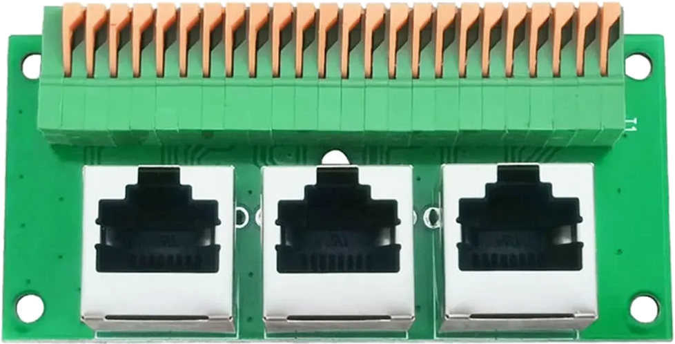
The RJ45 Female Breakout Board is a compact circuit board designed to provide easy access to the pins of an RJ45 connector. It allows users to interface with Ethernet cables for testing, prototyping, or custom wiring applications. This breakout board is particularly useful for engineers, hobbyists, and technicians working with Ethernet-based systems.
Explore Projects Built with RJ45 Female Breakout Board
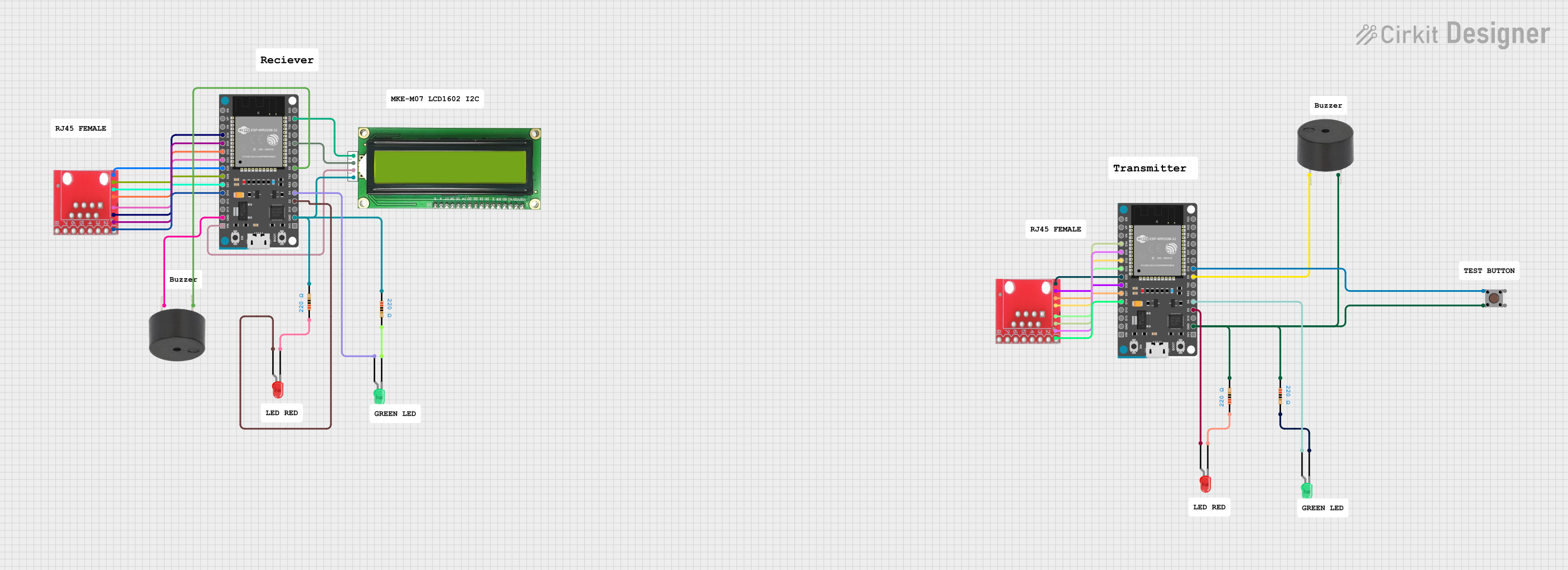
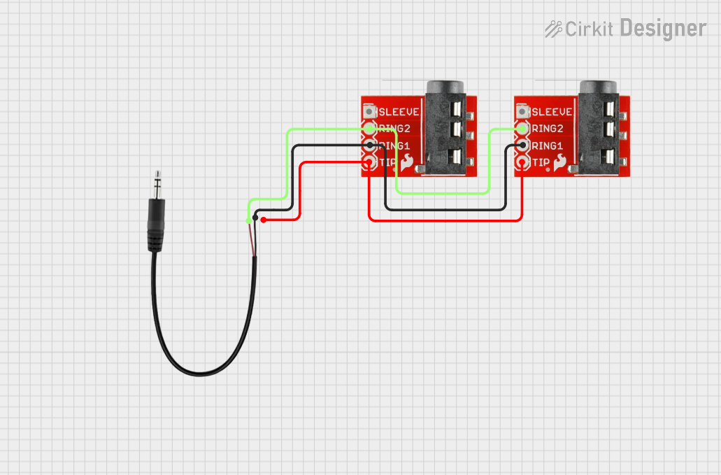


Explore Projects Built with RJ45 Female Breakout Board
Common Applications and Use Cases
- Prototyping Ethernet-based circuits and devices.
- Testing Ethernet cables for continuity and pin mapping.
- Interfacing microcontrollers or other devices with Ethernet networks.
- Educational purposes for learning about Ethernet pinouts and connections.
Technical Specifications
The RJ45 Female Breakout Board is designed to simplify Ethernet connections by breaking out the 8 pins of an RJ45 connector to labeled solder pads or terminal blocks.
Key Technical Details
- Connector Type: RJ45 Female (8P8C)
- Pin Count: 8 pins (1 to 8)
- Board Dimensions: Typically 25mm x 30mm (may vary by manufacturer)
- Mounting Options: Through-hole or screw terminal connections
- Voltage Rating: Supports standard Ethernet signal levels (3.3V or 5V logic compatible)
- Material: FR4 PCB with solder mask and silkscreen labeling
- Compatibility: Works with Cat5, Cat5e, and Cat6 Ethernet cables
Pin Configuration and Descriptions
The RJ45 Female Breakout Board maps the 8 pins of the RJ45 connector to labeled solder pads or terminal blocks. Below is the standard pinout for Ethernet cables:
| Pin Number | Signal Name | Description |
|---|---|---|
| 1 | TX+ | Transmit Data Positive |
| 2 | TX- | Transmit Data Negative |
| 3 | RX+ | Receive Data Positive |
| 4 | BI_D3+ | Bidirectional Data Line 3 Positive |
| 5 | BI_D3- | Bidirectional Data Line 3 Negative |
| 6 | RX- | Receive Data Negative |
| 7 | BI_D4+ | Bidirectional Data Line 4 Positive |
| 8 | BI_D4- | Bidirectional Data Line 4 Negative |
Note: The pinout follows the T568B Ethernet wiring standard, which is commonly used in networking.
Usage Instructions
How to Use the Component in a Circuit
- Connect the Ethernet Cable: Plug the RJ45 connector of your Ethernet cable into the female port on the breakout board.
- Access the Pins: Use the labeled solder pads or terminal blocks to connect the breakout board to your circuit.
- Wire to Your Device: Connect the breakout board pins to your microcontroller, testing equipment, or other devices as needed.
- Power Considerations: Ensure that the voltage levels on the connected device are compatible with Ethernet signal levels (typically 3.3V or 5V).
Important Considerations and Best Practices
- Avoid Overvoltage: Do not apply voltages higher than the rated levels to the breakout board pins.
- Cable Type: Use high-quality Ethernet cables (Cat5e or Cat6) for reliable connections.
- Signal Integrity: Keep wires as short as possible to minimize signal degradation.
- Static Protection: Handle the breakout board with care to avoid damage from electrostatic discharge (ESD).
Example: Connecting to an Arduino UNO
The RJ45 Female Breakout Board can be used to interface an Arduino UNO with Ethernet signals. Below is an example of how to read Ethernet signals using the breakout board:
/*
  Example: Reading Ethernet Signals with RJ45 Breakout Board
  This code demonstrates how to read digital signals from the RJ45 breakout board.
  Note: This example assumes the breakout board is connected to the Arduino's
  digital pins. Ensure proper wiring before running the code.
*/

const int rxPin = 2; // Pin connected to RX+ (Pin 3 on RJ45 breakout)
const int txPin = 3; // Pin connected to TX+ (Pin 1 on RJ45 breakout)

void setup() {
  pinMode(rxPin, INPUT); // Set RX pin as input
  pinMode(txPin, INPUT); // Set TX pin as input
  Serial.begin(9600);    // Initialize serial communication
}

void loop() {
  int rxSignal = digitalRead(rxPin); // Read RX signal
  int txSignal = digitalRead(txPin); // Read TX signal

  // Print the signal states to the Serial Monitor
  Serial.print("RX Signal: ");
  Serial.println(rxSignal);
  Serial.print("TX Signal: ");
  Serial.println(txSignal);

  delay(500); // Wait for 500ms before the next reading
}
Note: This example is for educational purposes and does not implement a full Ethernet protocol stack.
Troubleshooting and FAQs
Common Issues Users Might Face
No Signal Detected:
- Cause: Incorrect wiring or loose connections.
- Solution: Double-check the wiring and ensure the Ethernet cable is securely connected.
Signal Interference:
- Cause: Long wires or poor-quality cables.
- Solution: Use shorter wires and high-quality Ethernet cables (e.g., Cat5e or Cat6).
Damaged Pins:
- Cause: Excessive force or improper handling.
- Solution: Inspect the breakout board for physical damage and replace if necessary.
Incorrect Pin Mapping:
- Cause: Misunderstanding of the RJ45 pinout.
- Solution: Refer to the pin configuration table in this documentation.
Solutions and Tips for Troubleshooting
- Use a multimeter to verify continuity between the breakout board pins and the Ethernet cable.
- Test the breakout board with a known working Ethernet cable to rule out cable issues.
- If using with a microcontroller, ensure the GPIO pins are configured correctly in your code.
Tip: Always handle the breakout board with care to avoid damage from static electricity or physical stress.