Cirkit Designer Logo
Cirkit Designer
Your all-in-one circuit design IDE
Home / 
Component Documentation

How to Use Light Sensor w Relay: Examples, Pinouts, and Specs

Image of Light Sensor w Relay
Cirkit Designer LogoDesign with Light Sensor w Relay in Cirkit Designer

Introduction

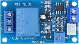
The XHM131 Light Sensor w Relay is a versatile electronic component designed to detect ambient light levels and activate a relay based on user-defined thresholds. This component is ideal for automating devices such as lights, fans, or other appliances, making it a popular choice for home automation, industrial applications, and DIY projects. Manufactured in China, the XHM131 combines a light-dependent resistor (LDR) for light detection and a relay module for switching high-power devices.

Explore Projects Built with Light Sensor w Relay

Use Cirkit Designer to design, explore, and prototype these projects online. Some projects support real-time simulation. Click "Open Project" to start designing instantly!
Battery-Powered Light-Activated Relay Circuit with Photocell and Transistor
Image of darshan: A project utilizing Light Sensor w Relay in a practical application
This circuit is a light-sensitive relay switch that uses a photocell (LDR) to control a 12V relay via a BC547 transistor. The relay is powered by a 12V battery, and the transistor acts as a switch that is triggered by the resistance change in the LDR, which is influenced by the ambient light level.
Cirkit Designer LogoOpen Project in Cirkit Designer
LDR-Activated Relay Control for Dual Bulb Illumination
Image of automatic headlight control project : A project utilizing Light Sensor w Relay in a practical application
This circuit appears to be a light-activated switch controlling two bulbs using a 5V relay, with an LDR (Light Dependent Resistor) as the sensor. The relay is powered by a 48V to 5V converter, which is switched on by a 12V battery through an SPST toggle switch. The LDR's output is connected to the relay's input, enabling the relay to switch the bulbs on or off based on the ambient light level detected by the LDR.
Cirkit Designer LogoOpen Project in Cirkit Designer
Arduino UNO-Based Smart Lighting System with Motion Detection and Energy Monitoring
Image of smart street light: A project utilizing Light Sensor w Relay in a practical application
This circuit is designed to monitor and control lighting based on ambient light levels and motion detection. It uses an Arduino UNO to read data from an LDR and two HC-SR501 motion sensors, and controls a 2-channel relay module to turn lights on or off. The system also measures current and voltage, displays these values on an LCD, and can be remotely controlled or monitored via the Blynk platform.
Cirkit Designer LogoOpen Project in Cirkit Designer
Wi-Fi Enabled Motion-Activated Lighting System with Radar Sensor
Image of CAPSTONE: A project utilizing Light Sensor w Relay in a practical application
This circuit is designed to control an AC LED bulb using a 220V power source, with an infrared motion sensor and an MMWave radar sensor providing input signals. The two-channel relay is used to switch the LED bulb on and off based on the sensor inputs, while the ESP8266 microcontroller is likely programmed to process the sensor data and control the relay. A converter is included to interface between the sensors, microcontroller, and the relay, ensuring proper voltage levels.
Cirkit Designer LogoOpen Project in Cirkit Designer

Explore Projects Built with Light Sensor w Relay

Use Cirkit Designer to design, explore, and prototype these projects online. Some projects support real-time simulation. Click "Open Project" to start designing instantly!
Image of darshan: A project utilizing Light Sensor w Relay in a practical application
Battery-Powered Light-Activated Relay Circuit with Photocell and Transistor
This circuit is a light-sensitive relay switch that uses a photocell (LDR) to control a 12V relay via a BC547 transistor. The relay is powered by a 12V battery, and the transistor acts as a switch that is triggered by the resistance change in the LDR, which is influenced by the ambient light level.
Cirkit Designer LogoOpen Project in Cirkit Designer
Image of automatic headlight control project : A project utilizing Light Sensor w Relay in a practical application
LDR-Activated Relay Control for Dual Bulb Illumination
This circuit appears to be a light-activated switch controlling two bulbs using a 5V relay, with an LDR (Light Dependent Resistor) as the sensor. The relay is powered by a 48V to 5V converter, which is switched on by a 12V battery through an SPST toggle switch. The LDR's output is connected to the relay's input, enabling the relay to switch the bulbs on or off based on the ambient light level detected by the LDR.
Cirkit Designer LogoOpen Project in Cirkit Designer
Image of smart street light: A project utilizing Light Sensor w Relay in a practical application
Arduino UNO-Based Smart Lighting System with Motion Detection and Energy Monitoring
This circuit is designed to monitor and control lighting based on ambient light levels and motion detection. It uses an Arduino UNO to read data from an LDR and two HC-SR501 motion sensors, and controls a 2-channel relay module to turn lights on or off. The system also measures current and voltage, displays these values on an LCD, and can be remotely controlled or monitored via the Blynk platform.
Cirkit Designer LogoOpen Project in Cirkit Designer
Image of CAPSTONE: A project utilizing Light Sensor w Relay in a practical application
Wi-Fi Enabled Motion-Activated Lighting System with Radar Sensor
This circuit is designed to control an AC LED bulb using a 220V power source, with an infrared motion sensor and an MMWave radar sensor providing input signals. The two-channel relay is used to switch the LED bulb on and off based on the sensor inputs, while the ESP8266 microcontroller is likely programmed to process the sensor data and control the relay. A converter is included to interface between the sensors, microcontroller, and the relay, ensuring proper voltage levels.
Cirkit Designer LogoOpen Project in Cirkit Designer

Common Applications and Use Cases

  • Automatic lighting systems (e.g., streetlights, garden lights)
  • Smart home automation
  • Energy-saving systems
  • Industrial equipment control
  • DIY electronics projects

Technical Specifications

Key Technical Details

  • Manufacturer Part ID: XHM131
  • Operating Voltage: 5V DC
  • Relay Output Voltage: 250V AC / 30V DC (max)
  • Relay Output Current: 10A (max)
  • Light Detection Range: Adjustable via onboard potentiometer
  • Trigger Type: Light-dependent (adjustable threshold)
  • Dimensions: 50mm x 26mm x 19mm
  • Operating Temperature: -40°C to 85°C

Pin Configuration and Descriptions

The XHM131 module has a total of 6 pins and terminals for input and output connections. Below is the pinout description:

Pin/Terminal Label Description
1 VCC Connect to a 5V DC power supply.
2 GND Ground connection.
3 OUT Digital output pin that indicates the light detection status (HIGH or LOW).
4 NC Normally Closed terminal of the relay.
5 COM Common terminal of the relay.
6 NO Normally Open terminal of the relay.

Usage Instructions

How to Use the Component in a Circuit

  1. Power the Module: Connect the VCC pin to a 5V DC power source and the GND pin to ground.
  2. Adjust the Sensitivity: Use the onboard potentiometer to set the light threshold at which the relay activates.
  3. Connect the Load:
    • For devices that should turn ON when light is detected, connect the load between the NO (Normally Open) and COM (Common) terminals.
    • For devices that should turn OFF when light is detected, connect the load between the NC (Normally Closed) and COM terminals.
  4. Monitor the Output: The OUT pin provides a digital signal (HIGH or LOW) that can be read by a microcontroller like an Arduino.

Important Considerations and Best Practices

  • Power Supply: Ensure a stable 5V DC power supply to avoid erratic behavior.
  • Load Ratings: Do not exceed the relay's maximum voltage (250V AC / 30V DC) or current (10A).
  • Isolation: For safety, ensure proper isolation between the high-voltage relay terminals and the low-voltage control circuit.
  • Potentiometer Adjustment: Turn the potentiometer clockwise to increase the light threshold or counterclockwise to decrease it.
  • Mounting: Secure the module in a well-ventilated area to prevent overheating.

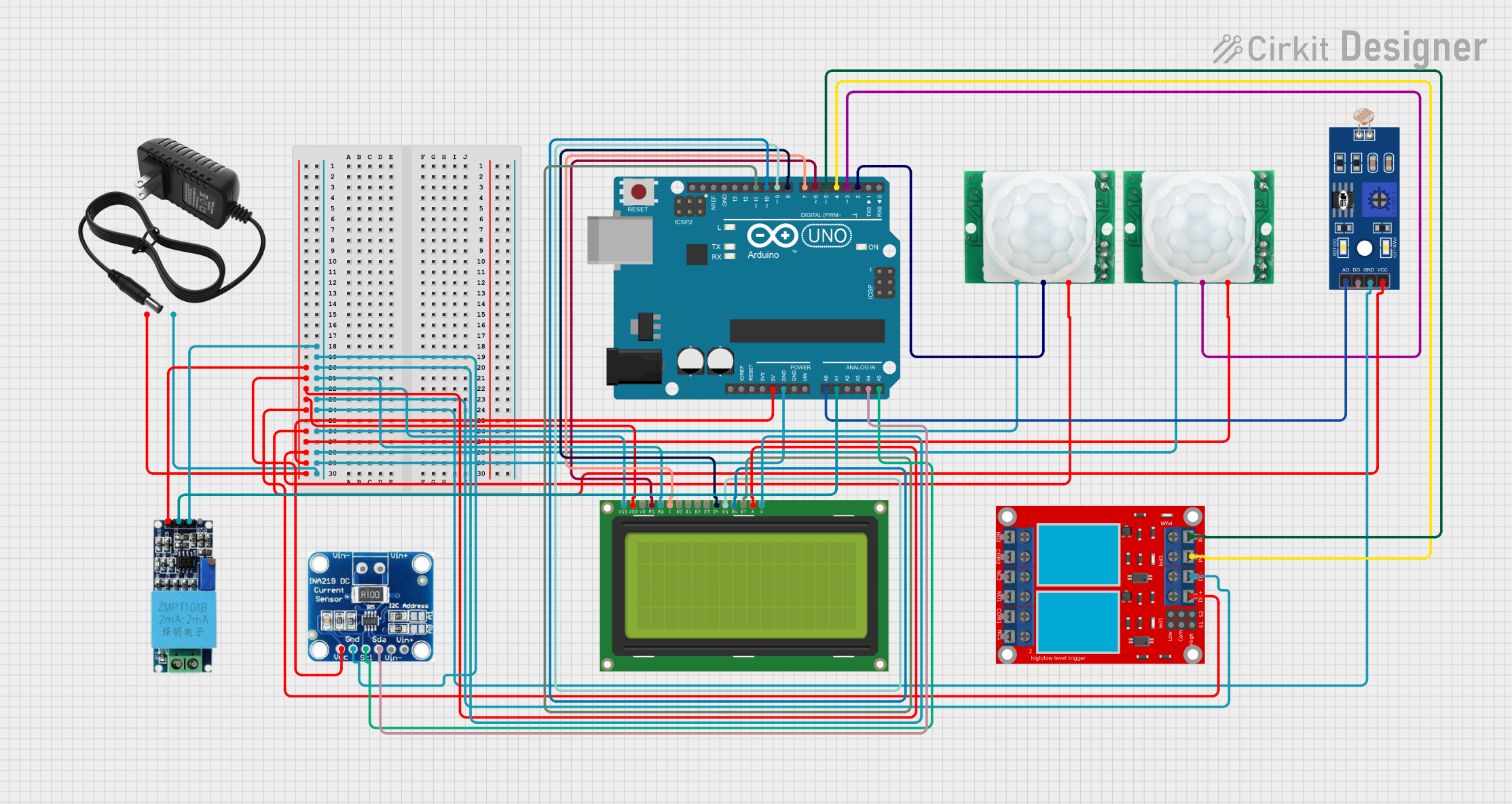
Example: Connecting to an Arduino UNO

Below is an example of how to use the XHM131 with an Arduino UNO to control an LED based on ambient light levels.

Circuit Connections

  • Connect the VCC and GND pins of the XHM131 to the 5V and GND pins of the Arduino, respectively.
  • Connect the OUT pin of the XHM131 to Arduino digital pin 2.
  • Connect an LED to the NO and COM terminals of the relay, with a suitable resistor in series.

Arduino Code

// Define the pin connected to the XHM131 OUT pin
const int lightSensorPin = 2;  
// Define the pin connected to the relay (NO terminal)
const int relayPin = 13;  

void setup() {
  pinMode(lightSensorPin, INPUT);  // Set the light sensor pin as input
  pinMode(relayPin, OUTPUT);       // Set the relay pin as output
  digitalWrite(relayPin, LOW);     // Ensure the relay is off initially
  Serial.begin(9600);              // Initialize serial communication
}

void loop() {
  int lightStatus = digitalRead(lightSensorPin);  // Read the light sensor output
  
  if (lightStatus == HIGH) {
    // If light is detected, activate the relay
    digitalWrite(relayPin, HIGH);
    Serial.println("Light detected: Relay ON");
  } else {
    // If no light is detected, deactivate the relay
    digitalWrite(relayPin, LOW);
    Serial.println("No light detected: Relay OFF");
  }
  
  delay(500);  // Add a small delay for stability
}

Troubleshooting and FAQs

Common Issues and Solutions

  1. Relay Not Activating

    • Cause: Insufficient power supply or incorrect wiring.
    • Solution: Verify that the VCC pin is receiving a stable 5V DC and check all connections.
  2. Erratic Behavior

    • Cause: Electrical noise or unstable power supply.
    • Solution: Use a decoupling capacitor (e.g., 100µF) across the VCC and GND pins to stabilize the power supply.
  3. Relay Stuck in One State

    • Cause: Incorrect potentiometer adjustment.
    • Solution: Adjust the potentiometer to set the desired light threshold.
  4. Arduino Not Detecting Output

    • Cause: Incorrect pin configuration or faulty module.
    • Solution: Ensure the OUT pin is connected to the correct Arduino pin and test the module with a multimeter.

FAQs

  • Q: Can the XHM131 detect specific light wavelengths?
    A: No, the XHM131 uses an LDR, which responds to general ambient light levels and is not wavelength-specific.

  • Q: Can I use the XHM131 with a 3.3V microcontroller?
    A: The module requires a 5V power supply, but the OUT pin can be connected to a 3.3V logic input with proper level shifting.

  • Q: Is the relay safe for inductive loads like motors?
    A: Yes, but use a flyback diode across the load to protect the relay from voltage spikes.

This concludes the documentation for the XHM131 Light Sensor w Relay.