Cirkit Designer Logo
Cirkit Designer
Your all-in-one circuit design IDE
Home / 
Component Documentation

How to Use Adafruit Feather M0 RFM9x LoRa: Examples, Pinouts, and Specs

Image of Adafruit Feather M0 RFM9x LoRa
Cirkit Designer LogoDesign with Adafruit Feather M0 RFM9x LoRa in Cirkit Designer

Introduction

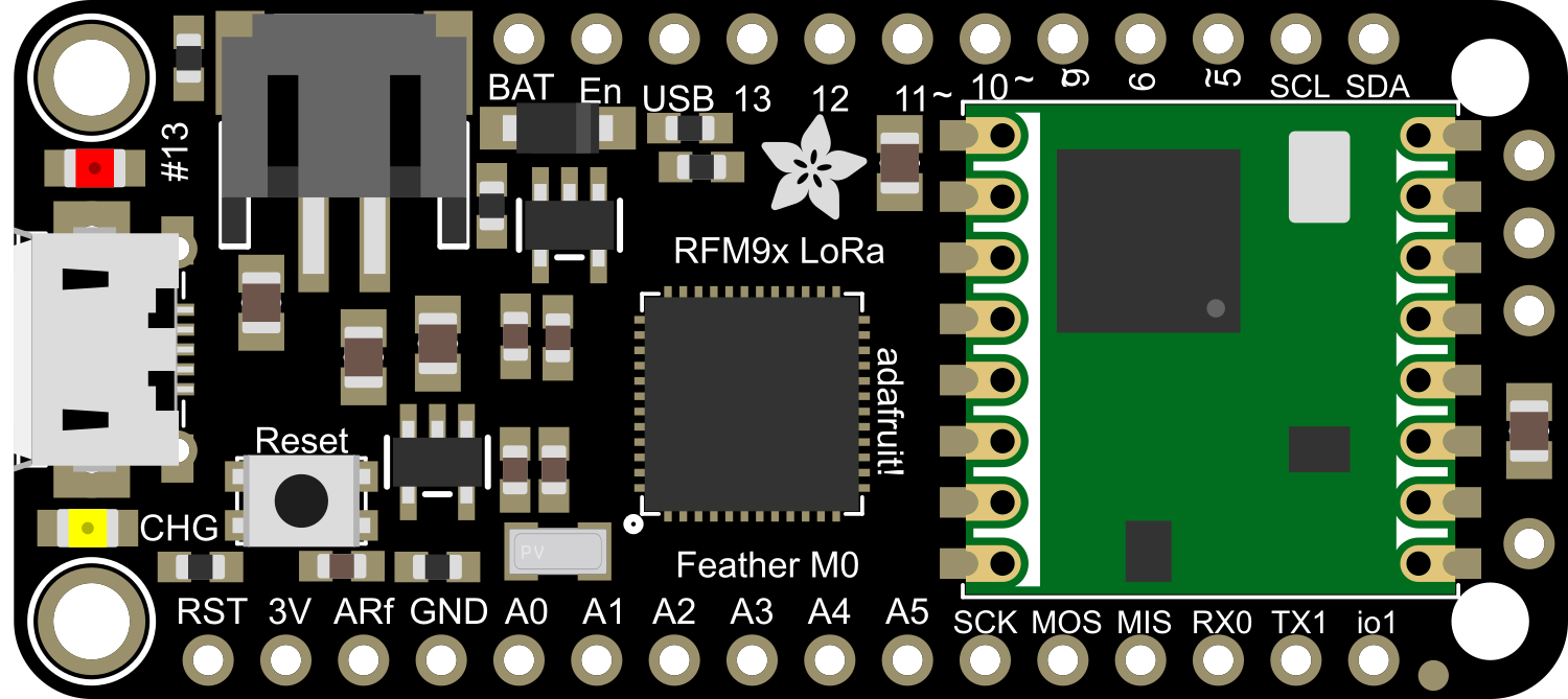
The Adafruit Feather M0 RFM9x LoRa is a versatile, compact development board that combines the power of the ATSAMD21G18 ARM Cortex M0 microcontroller with the long-range communication capabilities of the RFM9x LoRa radio module. This board is ideal for projects requiring wireless data transmission over long distances with minimal power usage, such as remote sensors, home automation, and IoT applications.

Explore Projects Built with Adafruit Feather M0 RFM9x LoRa

Use Cirkit Designer to design, explore, and prototype these projects online. Some projects support real-time simulation. Click "Open Project" to start designing instantly!
Arduino MKR WiFi 1010 and Adafruit RFM9x LoRa Radio Communication System
Image of 1010: A project utilizing Adafruit Feather M0 RFM9x LoRa in a practical application
This circuit connects an Adafruit RFM9x LoRa Radio module to an Arduino MKR WiFi 1010 for wireless communication capabilities. The LoRa module's SPI interface (MOSI, MISO, SCK, CS) is connected to the corresponding SPI pins on the Arduino, allowing for serial data transfer between the devices. Additionally, the LoRa module's reset (RST) and interrupt (DIO0) pins are connected to digital pins on the Arduino for control and asynchronous communication.
Cirkit Designer LogoOpen Project in Cirkit Designer
ESP32-Controlled LoRa Communication Module
Image of receiver: A project utilizing Adafruit Feather M0 RFM9x LoRa in a practical application
This circuit connects an ESP32 microcontroller to an Adafruit RFM9x LoRa Radio module for wireless communication. The ESP32's GPIO pins are wired to the LoRa module's SPI interface (MOSI, MISO, SCK, CS), interrupt (DIO0), and reset (RST) to enable data transmission and reception over LoRa. The ESP32 also provides power (3V3) and ground (GND) to the LoRa module.
Cirkit Designer LogoOpen Project in Cirkit Designer
Xiao ESP32 C3 and Adafruit RFM9x LoRa Radio Communication Module
Image of LoRa: A project utilizing Adafruit Feather M0 RFM9x LoRa in a practical application
This circuit connects a Xiao ESP32 C3 microcontroller to an Adafruit RFM9x LoRa Radio module. The ESP32 C3 provides power to the LoRa module and interfaces with it using SPI communication (SCK, MISO, MOSI, CS) and control lines (RST, DIO0). This setup is likely intended for wireless communication using LoRa technology, with the ESP32 handling data processing and network protocol tasks.
Cirkit Designer LogoOpen Project in Cirkit Designer
ESP32 and RFM95 LoRa Transmitter with Inductor-Based Antenna
Image of transmitter LoRa: A project utilizing Adafruit Feather M0 RFM9x LoRa in a practical application
This circuit is a LoRa transmitter system that uses an ESP32 microcontroller to communicate with an RFM95 LoRa module. The ESP32 initializes the LoRa module and sends periodic messages wirelessly, with an inductor connected to the antenna pin of the RFM95 for signal tuning.
Cirkit Designer LogoOpen Project in Cirkit Designer

Explore Projects Built with Adafruit Feather M0 RFM9x LoRa

Use Cirkit Designer to design, explore, and prototype these projects online. Some projects support real-time simulation. Click "Open Project" to start designing instantly!
Image of 1010: A project utilizing Adafruit Feather M0 RFM9x LoRa in a practical application
Arduino MKR WiFi 1010 and Adafruit RFM9x LoRa Radio Communication System
This circuit connects an Adafruit RFM9x LoRa Radio module to an Arduino MKR WiFi 1010 for wireless communication capabilities. The LoRa module's SPI interface (MOSI, MISO, SCK, CS) is connected to the corresponding SPI pins on the Arduino, allowing for serial data transfer between the devices. Additionally, the LoRa module's reset (RST) and interrupt (DIO0) pins are connected to digital pins on the Arduino for control and asynchronous communication.
Cirkit Designer LogoOpen Project in Cirkit Designer
Image of receiver: A project utilizing Adafruit Feather M0 RFM9x LoRa in a practical application
ESP32-Controlled LoRa Communication Module
This circuit connects an ESP32 microcontroller to an Adafruit RFM9x LoRa Radio module for wireless communication. The ESP32's GPIO pins are wired to the LoRa module's SPI interface (MOSI, MISO, SCK, CS), interrupt (DIO0), and reset (RST) to enable data transmission and reception over LoRa. The ESP32 also provides power (3V3) and ground (GND) to the LoRa module.
Cirkit Designer LogoOpen Project in Cirkit Designer
Image of LoRa: A project utilizing Adafruit Feather M0 RFM9x LoRa in a practical application
Xiao ESP32 C3 and Adafruit RFM9x LoRa Radio Communication Module
This circuit connects a Xiao ESP32 C3 microcontroller to an Adafruit RFM9x LoRa Radio module. The ESP32 C3 provides power to the LoRa module and interfaces with it using SPI communication (SCK, MISO, MOSI, CS) and control lines (RST, DIO0). This setup is likely intended for wireless communication using LoRa technology, with the ESP32 handling data processing and network protocol tasks.
Cirkit Designer LogoOpen Project in Cirkit Designer
Image of transmitter LoRa: A project utilizing Adafruit Feather M0 RFM9x LoRa in a practical application
ESP32 and RFM95 LoRa Transmitter with Inductor-Based Antenna
This circuit is a LoRa transmitter system that uses an ESP32 microcontroller to communicate with an RFM95 LoRa module. The ESP32 initializes the LoRa module and sends periodic messages wirelessly, with an inductor connected to the antenna pin of the RFM95 for signal tuning.
Cirkit Designer LogoOpen Project in Cirkit Designer

Technical Specifications

Microcontroller:

  • Chip: ATSAMD21G18, 32-bit ARM Cortex M0+
  • Clock Speed: 48 MHz
  • Flash Memory: 256 KB
  • SRAM: 32 KB
  • Voltage: 3.3V logic and power

LoRa Radio:

  • Frequency: 433 MHz or 868/915 MHz (region-specific)
  • Modulation: LoRa spread spectrum
  • Output Power: Up to +20 dBm
  • Sensitivity: Down to -148 dBm
  • Range: Up to 2 km with provided wire antenna (line-of-sight)

General:

  • Operating Voltage: 3.7V to 6V (via LiPo battery or USB power)
  • Battery Charging: 100mA lithium polymer battery charging via USB
  • I/O Pins: 20 GPIO pins
  • Interfaces: UART, I2C, SPI
  • Analog Inputs: 6 x 12-bit ADC channels
  • PWM Outputs: Up to 10
  • Dimensions: 51mm x 23mm x 8mm

Pin Configuration and Descriptions

Pin # Function Description
1 GND Ground
2 3V3 3.3V power supply output
3 AREF Analog reference voltage for ADC
4-9 A0-A5 Analog input pins
10-17 D0-D7 Digital I/O pins
18 SCK SPI clock
19 MISO SPI Master In Slave Out
20 MOSI SPI Master Out Slave In
21 RX UART receive pin
22 TX UART transmit pin
23 SDA I2C data line
24 SCL I2C clock line
25 RST Reset pin
26 RFM9x_RST LoRa radio module reset pin
27 RFM9x_CS LoRa radio module chip select
28 RFM9x_INT LoRa radio module interrupt pin
29 BAT Battery voltage (analog input)
30 USB USB data-
31 USB USB data+

Usage Instructions

Integration into a Circuit

To integrate the Adafruit Feather M0 RFM9x LoRa into a circuit:

  1. Powering the Board: Connect a 3.7V LiPo battery for portable applications or power the board via the USB connection.
  2. Antenna: Attach the provided wire antenna to the ANT pin for LoRa communication.
  3. Programming: Use the micro USB port to connect the board to a computer for programming via the Arduino IDE.
  4. I/O Connections: Utilize the GPIO pins for connecting sensors, actuators, or other peripherals as required by your project.

Best Practices

  • Always ensure that the power supply is within the specified range to prevent damage.
  • When using the LoRa radio, ensure that the antenna is properly connected and positioned for optimal range.
  • Follow ESD precautions when handling the board to avoid damaging the sensitive electronic components.

Example Code for Arduino UNO

Here is a basic example of how to send data using the LoRa radio on the Adafruit Feather M0 RFM9x LoRa. This code should be uploaded to the Feather M0 board.

#include <SPI.h>
#include <RH_RF95.h>

// Singleton instance of the radio driver
RH_RF95 rf95;

void setup() {
  Serial.begin(9600);
  while (!Serial) {
    ; // Wait for serial port to be available
  }
  if (!rf95.init()) {
    Serial.println("LoRa radio init failed");
    while (1);
  }
  Serial.println("LoRa radio init OK!");
  if (!rf95.setFrequency(915.0)) {
    Serial.println("setFrequency failed");
    while (1);
  }
  rf95.setTxPower(13, false);
}

void loop() {
  const char *msg = "Hello World!";
  rf95.send((uint8_t *)msg, strlen(msg));
  rf95.waitPacketSent();
  Serial.println("Sent a message!");
  delay(1000);
}

Ensure that you have the RadioHead library installed in your Arduino IDE to use the RH_RF95 class.

Troubleshooting and FAQs

Common Issues

  • Board not recognized by computer: Check the USB cable and port. Try a different cable or port if necessary.
  • LoRa communication failure: Ensure the antenna is properly connected and not damaged. Check the frequency and settings match between sender and receiver.
  • Battery not charging: Verify the battery is properly connected and the USB port can supply sufficient current for charging.

FAQs

Q: Can I use the Feather M0 with a different frequency LoRa module? A: Yes, but ensure you have the correct version of the board for your region's frequency regulations.

Q: What is the maximum range I can achieve with the LoRa radio? A: The range can vary greatly depending on the environment, but with line-of-sight and proper antenna setup, you can achieve up to 2 km.

Q: How do I program the Feather M0? A: You can program it using the Arduino IDE. Select the 'Adafruit Feather M0' board from the board manager.

For further assistance, consult the Adafruit Feather M0 RFM9x LoRa forums and support channels.